Decca Navigator System

Last updated

Accuracy of Navigation Systems.svg
The display panel of a Decca Navigator Mk 12 (ca. 1962). Decca position coordinates were directly displayed by four decometers and these were plotted on a conventional chart that had been over-printed with Decca lattices. Decca Navigator Mk 12.jpg
The display panel of a Decca Navigator Mk 12 (ca. 1962). Decca position coordinates were directly displayed by four decometers and these were plotted on a conventional chart that had been over-printed with Decca lattices.

The Decca Navigator System was a hyperbolic radio navigation system that allowed ships and aircraft to determine their position by using radio signals from a dedicated system of static radio transmitters. The system used phase comparison of two low frequency signals between 70 and 129 kHz, as opposed to pulse timing systems like Gee and LORAN. This made it much easier to design receivers using 1940s electronics, and operation was simplified by giving a direct readout of Decca coordinates without the complexity of a cathode ray tube and highly skilled operator.

Contents

The system was invented and developed by Decca in the UK. It was first deployed by the Royal Navy during World War II for the vital task of clearing the minefields to enable the D-Day landings. The Allied forces needed an accurate system not known to the Germans and thus free of jamming. After the war, it came off the secret list and was commercially developed by the Decca Company and deployed around UK and later used in many areas around the world. At its peak there were about 180 transmitting stations using "chains" of three or four transmitters each to allow position fixing by plotting intersecting electronic lines. Decca's primary use was for ship navigation in coastal waters, offering much better accuracy than the competing LORAN system. Fishing vessels were major post-war users, but it was also used on some aircraft, including a very early (1949) application of moving map displays. The system was deployed extensively in the North Sea and was used by helicopters operating to oil platforms.

The opening of the more accurate Loran-C system to civilian use in 1974 offered stiff competition, but Decca was well established by this time and continued operations to 2000. Decca Navigator was eventually replaced, along with Loran and similar systems, by the GPS in 2000, when that became available for public use.

Principles of operation

Overview

The Decca Navigator principle.
The phase difference between the signals received from stations A (Master) and B (Secondary) is constant along each hyperbolic curve. The foci of the hyperbolas are at the transmitting stations, A and B. Crude loran diagram.PNG
The Decca Navigator principle.
The phase difference between the signals received from stations A (Master) and B (Secondary) is constant along each hyperbolic curve. The foci of the hyperbolas are at the transmitting stations, A and B.

The Decca Navigator System consisted of individual groups of land-based radio transmitters organised into chains of three or four stations. Each chain consisted of a master station and three (occasionally two) secondary stations, termed Red, Green and Purple. Ideally, the secondaries would be positioned at the vertices of an equilateral triangle with the master at the centre. The baseline length, that is, the master-secondary distance, was typically 60–120 nautical miles (110–220 km).

Each station transmitted a continuous wave signal that, by comparing the phase difference of the signals from the master and one of the secondaries, produced a relative phase measure that was presented on a clock-like display. The phase difference was caused by the relative distance between the stations as seen by the receiver. As the receiver moves these distances change and those changes are represented by the movement of the hands on the displays.

If one selects a particular phase difference, say 30 degrees, and plots all the locations where that phase difference occurs, the result is a set of hyperbolic lines of position called a pattern. As there were three secondaries there were three patterns, also termed Red, Green and Purple. The patterns were drawn on nautical charts as a set of hyperbolic lines in the appropriate colour.

Receivers determined their location by measuring the phase difference from two or more of the patterns from the displays. They could then look at the chart to find where the two closest charted hyperbolas crossed. The accuracy of this measurement was improved by choosing the set of two patterns that resulted in the lines crossing at as close to a right angle as possible.

Detailed principles of operation

When two stations transmit at the phase-locked frequency, the difference in phase between the two signals is constant along a hyperbolic path. If two stations transmit on the same frequency, it is impossible for the receiver to separate them. Instead, each chain was allocated a nominal frequency, known as 1f, and each station in the chain transmitted at a harmonic of this base frequency, as follows:

StationHarmonicFrequency (kHz)
Master6f85.000
Purple5f70.833
Red8f113.333
Green9f127.500

The frequencies given are those for Chain 5B, known as the English Chain, but all chains used similar frequencies between 70 kHz and 129 kHz.

Decca receivers multiplied the signals received from the Master and each Slave by different values to arrive at a common frequency (least common multiple, LCM) for each Master/Slave pair, as follows:

PatternSlave HarmonicSlave MultiplierMaster HarmonicMaster MultiplierCommon Frequency
Purple5f×66f×530f
Red8f×36f×424f
Green9f×26f×318f

It was phase comparison at this common frequency that resulted in the hyperbolic lines of position. The interval between two adjacent hyperbolas on which the signals are in phase was called a lane. Since the wavelength of the common frequency was small compared with the distance between the Master and Slave stations there were many possible lines of position for a given phase difference, and so a unique position could not be arrived at by this method.

Other receivers, typically for aeronautical applications, divided the transmitted frequencies down to the basic frequency (1f) for phase comparison, rather than multiplying them up to the LCM frequency.

Lanes and zones

A 1967 Admiralty Decca Chart of the Thames Estuary, marked with red and green lanes and zones. Admiralty Chart No 1607 Thames Estuary Southern Part, Published 1967.jpg
A 1967 Admiralty Decca Chart of the Thames Estuary, marked with red and green lanes and zones.

Early Decca receivers were fitted with three rotating Decometers that indicated the phase difference for each pattern. Each Decometer drove a second indicator that counted the number of lanes traversed each 360 degrees of phase difference was one lane traversed. In this way, assuming the point of departure was known, a more or less distinct location could be identified.

The lanes were grouped into zones, with 18 green, 24 red, or 30 purple lanes in each zone. This meant that on the baseline (the straight line between the Master and its Slave) the zone width was the same for all three patterns of a given chain. Typical lane and zone widths on the baseline are shown in the table below (for chain 5B):

Lane or ZoneWidth on Baseline
Purple lane352.1 m
Red lane440.1 m
Green lane586.8 m
Zones (all patterns)10563 m

The lanes were numbered 0 to 23 for red, 30 to 47 for green and 50 to 79 for purple. The zones were labelled A to J, repeating after J. A Decca position coordinate could thus be written: Red I 16.30; Green D 35.80. Later receivers incorporated a microprocessor and displayed a position in latitude and longitude.

Multipulse

Multipulse provided an automatic method of lane and zone identification by using the same phase comparison techniques described above on lower frequency signals.

The nominally continuous wave transmissions were in fact divided into a 20-second cycle, with each station in turn simultaneously transmitting all four Decca frequencies (5f, 6f, 8f and 9f) in a phase-coherent relationship for a brief period of 0.45 seconds each cycle. This transmission, known as Multipulse, allowed the receiver to extract the 1f frequency and so to identify the lane that the receiver was in (to a resolution of a zone).

As well as transmitting the Decca frequencies of 5f, 6f, 8f and 9f, an 8.2f signal, known as Orange, was also transmitted. The beat frequency between the 8.0f (Red) and 8.2f (Orange) signals allowed a 0.2f signal to be derived and so resulted in a hyperbolic pattern in which one cycle (360°) of phase difference equates to 5 zones.

Assuming that one's position was known to this accuracy, this gave an effectively unique position.

Range and accuracy

During daylight, ranges of around 400 nautical miles (740 km) could be obtained, reducing at night to 200 to 250 nautical miles (460 km), depending on propagation conditions.

The accuracy depended on:

By day these errors could range from a few meters on the baseline up to a nautical mile at the edge of coverage. At night, skywave errors were greater and, on receivers without multipulse capabilities, it was not unusual for the position to jump a lane, sometimes without the navigator knowing.

Although in the days of differential GPS this range and accuracy may appear poor, in its day the Decca system was one of the few, if not the only, position fixing system available to many mariners. Since the need for an accurate position is less when the vessel is further from land, the reduced accuracy at long ranges was not a great problem.

History

Decca Navigator Mk. 21, with the Decometer dials prominent. Decca Navigator Mk 21.jpg
Decca Navigator Mk. 21, with the Decometer dials prominent.

Origins

In 1936 William J. O'Brien, an engineer, contracted tuberculosis that put his career on hold for a period of two years. During this period he had the idea of position fixing by means of phase comparison of continuous wave transmissions. This was not the first such system, but O'Brien apparently developed his version without knowledge of the others, and made several advancements in the art that would prove useful. He initially imagined the system being used for aircraft testing, specifically the accurate calculation of ground speed. Some experiments were carried out in California in 1938, selecting frequencies with harmonic "beats" that would allow for station identification in a network of transmitters. Both the U.S. Army and Navy considered the idea too complicated and work ended in 1939. [1]

O’Brien's friend, Harvey F. Schwarz, was chief engineer of the Decca Record company in England. In 1939 O’Brien sent him details of the system so it could be put forward to the British military. Initially Robert Watson-Watt reviewed the system but he did not follow it up, deeming it too easily jammed (and likely due to the existing work on the Gee system, being carried out by Watt's group). [2] However, in October 1941 the British Admiralty Signal Establishment (ASE) became interested in the system, which was then classified as Admiralty Outfit QM. The first marine trials were conducted between Anglesey and the Isle of Man, at frequencies of 305/610 kHz, on 16 September 1942. [1]

Further trials were conducted in the northern Irish Sea in April 1943 at 70/130 kHz. It was decided that the original frequencies were not ideal, and a new system using a 14 kHz inter-signal spacing was selected. This led to the common 5, 6, 8 and 9f frequencies, used throughout the life of the Decca system. 7f was reserved for a Loran-C-like extension, but never developed. [2] A follow-up test was carried out in the Irish Sea in January 1944 to test a wide variety of upgrades and production equipment. By this time the competing Gee system was known to the Admiralty and the two systems were tested head-to-head under the code names QM and QH. QM was found to have better sea-level range and accuracy, which led to its adoption. [2]

D-Day landings

A three-station trial was held in conjunction with a large-scale assault and landing exercise in the Moray Firth in February/March 1944. The success of the trials and the relative ease of use and accuracy of the system resulted in Decca receiving an order for 27 Admiralty Outfit QM receivers. The receiver consisted of an electronics unit with two dials and was known to its operators as the "Blue Gasmeter Job". A Decca chain was set up, consisting of a master station at Chichester and slaves at Swanage and Beachy Head. A fourth decoy transmitter was located in the Thames Estuary as part of the deception that the invasion would be focussed on the Calais area. 21 minesweepers and other vessels were fitted with Admiralty Outfit QM and, on 5 June 1944, 17 of these ships used it to accurately navigate across the English Channel and to sweep the minefields in the planned areas. The swept areas were marked with buoys in preparation for the Normandy Landings.

After the initial ship tests, Decca conducted tests in cars, driving in the Kingston By-Pass area to verify receiver accuracy. In the car installation, it was found possible to navigate within an individual traffic lane. The company entertained high hopes that the system could be used in aircraft, to permit much more precise navigation in the critical airspace around airports and urban centres where traffic density was highest.

Commercial deployment

Decca receiver, Mk.51 seen in the National Museum of Scotland DECCA unit, NMS.jpg
Decca receiver, Mk.51 seen in the National Museum of Scotland

After the end of World War II the Decca Navigator Co. Ltd. was formed (1945) and the system expanded rapidly, particularly in areas of British influence; at its peak it was deployed in many of the world's major shipping areas. More than 15,000 receiving sets were in use aboard ships in 1970. There were 4 chains around England, 1 in Ireland and 2 in Scotland, 12 in Scandinavia (5 each in Norway and Sweden and 1 each in Denmark and Finland), a further 4 elsewhere in northern Europe and 2 in Spain.

Canada was another early user, with branch offices set up in Toronto in 1953. [3] [ failed verification ] The first chain was installed in southwest Newfoundland in 1956 as part of a joint Canada-US Navy surveying program. This led to commercial deployments the next year in Nova Scotia and an inland system for air traffic in the busy Quebec City-Montreal area. A fourth chain covering eastern Newfoundland was added in 1958. When meetings in Montreal in 1958 led to VOR and DME being selected as the standard aviation navigation systems, the Montreal system was moved eastward to cover the Anticosti Island area of the Gulf of St. Lawrence, and the western Newfoundland chain was later repositioned to better cover the Cabot Strait. A series of chains was also proposed to cover the Northwest Passage had oil tanker traffic used the area, but this never came to be. Another was briefly set up covering Lake Ontario in 1971 for the International Field Year for the Great Lakes. [4] The last Canadian chain shut down in 1986, after Loran-C became widespread.

In the late 1950s an experimental Decca chain was set up in the United States, in the New York area, to be used for navigating the Vertol 107 helicopters of New York Airways. These helicopters were operating from the principal local airports—Idlewild Airport on Long Island, Newark Airport in New Jersey, LaGuardia Airport in the Borough of Queens, nearer to Manhattan, and a site on the top of the (then) PanAm Building on Park Avenue. Use of Decca was essential because its signals could be received down to sea level, were not subject to the line-of-sight limitations of VOR/DME and did not suffer the slant-range errors that create problems with VOR/DME close to the transmitters. The Decca installations in the New York Airways helicopters included the unique Decca 'roller map' displays that enabled the pilot to see his or her position at a glance, a concept infeasible with VOR/DME.

This chain installation was considered highly controversial at the time, for political reasons. This led to the U.S. Coast Guard, under instructions from the Treasury Department to which it reported, banning the use of Decca receivers in ships entering New York harbour for fear that the system might create a de facto standard (as it had become in other areas of the world). It also served to protect the marketing interests of the Hoffman Electronics division of ITT, a principal supplier of VOR/DME systems, that Decca might have been poised to usurp.

This situation was exacerbated by the workload problems of the Air Traffic Controllers Association (ATCA), under its executive director Francis McDermott, whose members were forced to use radar data on aircraft positions, relaying those positions by radio to the aircraft from their control locations. An example of the problem, cited by experts, was the collision of a Douglas DC8 and a Lockheed Constellation over Staten Island, New York, [5] that—according to some experts—could have been avoided if the aircraft had been Decca-equipped and could not only have determined their positions more precisely but would not have suffered from the rho-theta position errors inherent in VOR/DME.

Other chains were established in Japan (6 chains); Namibia and South Africa (5 chains); India and Bangladesh (4 chains); North-West Australia (2 chains); the Persian Gulf (1 chain with stations in Qatar and the United Arab Emirates and a second chain in the north of the Gulf with stations in Iran) and the Bahamas (1 chain). Four chains were planned for Nigeria but only two were built and these did not enter into public service. Two chains in Vietnam were used during the Vietnam War for helicopter navigation, with limited success. During the Cold War period, following WWII, the R.A.F. established a confidential chain in Germany. The Master station was in Bad Iburg near Osnabrück and there were two Slaves. The purpose of this chain was to provide accurate air navigation for the corridor between Western Germany and Berlin in the event that a mass evacuation of allied personnel may be required. In order to maintain secrecy, frequencies were changed at irregular intervals.

Decca, Racal, and the closedown

An ap Decca receiver Mk II from the 1980s that could be purchased instead of leased. It could store 25 waypoints. Decca Receiver Philips.jpg
An ap Decca receiver Mk II from the 1980s that could be purchased instead of leased. It could store 25 waypoints.

The headquarters of Decca Navigator were at New Malden, Surrey, just off the Kingston by-pass. There was a Decca School, at Brixham, Devon, where employees were sent on courses from time to time. Racal, the UK weapons and communications company, acquired Decca in 1980. Merging Decca's radar assets with their own, Racal began selling off the other portions of the company, including avionics and Decca Navigator.

A significant amount of income from the Decca system was due to the receivers being leased to users, not sold outright. This guaranteed predictable annual income. When the patents on the original technology lapsed in the early 1980s, new receivers were quickly built by a number of companies. In particular, Aktieselskabet Dansk Philips ('Danish Philips', ap) introduced receivers that could be purchased outright, and were much smaller and easier to use than the current Decca counterparts. The "ap" versions directly output the longitude and latitude to two decimals (originally in datum ED50 only) instead of using the "deco meter" displays, offering accuracy better than ±9.3 m[ citation needed ], much better than the Decca units. This also eliminated the need for the special charts printed with Decca lanes and zones.

Decca sued ap for infringement and, in the ensuing court battle, Decca lost the monopoly. That signalled the beginning of the end for the company. Income dwindled and eventually, the UK Ministry of Transport stepped in, having the lighthouse authorities take responsibility for operating the system in the early 1990s.

A ruling from the European Union forced the UK government to withdraw funding. The general lighthouse authority ceased Decca transmissions at midnight on 31 March 2000. The Irish chain provided by Bórd Iascaigh Mhara continued transmitting until 19 May 2000. Japan continued operating their Hokkaidō chain until March 2001, the last Decca chain in operation.

Other applications

Delrac

In the immediate post-war era, Decca began studying a long-range system like Decca, but using much lower frequencies to enable reception of skywaves at long distances. In February 1946 the company proposed a system with two main stations located at Shannon Airport in Ireland and Gander International Airport in Newfoundland (today part of Canada). Together, these stations would provide navigation over the main great circle route between London and New York. A third station in Bermuda would provide general ranging information to measure progress along the main track. [6]

Work on this concept continued, and in 1951 a modified version was presented that offered navigation over very wide areas. This was known as Delrac, short for "Decca Long Range Area Cover". A further development, including features of the General Post Office's POPI system, was introduced in 1954, proposing 28 stations that provided worldwide coverage. [6] The system was predicted to offer 10 miles (16,000 m) accuracy at 2,000 miles (3,200 km) range 95% of the time. Further development was ended in favour of the Dectra system. [7]

Dectra

In the early 1960s the Radio Technical Commission for Aeronautics (RTCA), as part of a wider ICAO effort, began the process of introducing a standard long-range radio navigation system for aviation use. Decca proposed a system that could offer both high-accuracy at short ranges and trans-Atlantic navigation with less accuracy, using a single receiver. The system was known as Dectra, short for "Decca Track". [7]

Unlike the Delrac system, Dectra was essentially the normal Decca Navigator system with the modification of several existing transmitter sites. [7] These were located at the East Newfoundland and Scottish chains, which were equipped with larger antennas and high-power transmitters, broadcasting 20 times as much energy as normal chain stations. Given that the length of the chain baselines did not change, and were relatively short, at long distance the signal offered almost no accuracy. Instead, Dectra operated as a track system; aircraft would navigate by keeping themselves within the signal defined by a particular Decca lane. [8]

The main advantage of Dectra compared to other systems being proposed for the RTCA solution was that it could be used for both medium-range navigation over land, as well as long-range navigation over the Atlantic. In comparison, the VOR/DME system that ultimately won the competition offered navigation over perhaps a 200-mile radius, and could not offer a solution to the long-distance problem. [8] Additionally, as the Decca system provided an X and Y location, as opposed to the angle-and-range VOR/DME, Decca proposed offering it with their Decca Flight Log moving map display to further improve ease of navigation. In spite of these advantages, the RTCA ultimately chose VOR/DME for two primary reasons; VOR offered coverage over about the same range as Decca, about 200 miles, but did so with a single transmitter instead of Decca's four, and Decca's frequencies proved susceptible to interference from static due to lightning, while VOR's higher frequencies were not quite as sensitive. [6]

Decca continued to propose that Dectra be used for the long-range role. In 1967 they installed another transmitter in Iceland to provide ranging along the Scotland-Newfoundland track, with a second proposed to be installed on the Azores. They also installed Dectra receivers with Omnitrac computers and a lightweight version of the Flight Log on a number of commercial airliners, notably a BOAC Vickers VC10. The Omnitrac could take inputs from Decca (and Dectra), Loran-C, VOR/DME, an air data computer and doppler radars and combine them all to produce a lat/long output along with bearing, distance-to-go, bearing and an autopilot coupling. [9] Their efforts to standardize this were eventually abandoned as inertial navigation systems began to be installed for these needs. [8]

Hi-Fix

A more accurate system named Hi-Fix was developed using signalling in the 1.6 MHz range. It was used for specialised applications such as precision measurements involved with oil-drilling and by the Royal Navy for detailed mapping and surveying of coasts and harbours. The Hi-Fix equipment was leased for a period with temporary chains established to provide coverage of the area required, Hi-Fix was commercialised by Racal Survey in the early 1980s. An experimental chain was installed with coverage of central London and receivers placed in London buses and other vehicles to demonstrate an early vehicle location and tracking system. Each vehicle would report its location automatically via a conventional VHF two-way radio link, the data added to a voice channel.

Another application was developed by the Bendix Pacific division of Bendix Corporation, with offices in North Hollywood, California, but not deployed: PFNS—Personal Field Navigation System—that would enable individual soldiers to ascertain their geographic position, long before this capability was made possible by the satellite-based GPS (Global Positioning System).

A further application of the Decca system was implemented by the U.S. Navy in the late 1950s and early 1960s for use in the Tongue of the Ocean/Eleuthera Sound area near The Bahamas, separating the islands of Andros and New Providence. The application was for sonar studies made possible by the unique characteristics of the ocean floor.

An interesting characteristic of the Decca VLF signal discovered on BOAC, later British Airways, test flights to Moscow, was that the carrier switching could not be detected even though the carrier could be received with sufficient strength to provide navigation.[ clarification needed ] Such testing, involving civilian aircraft, is quite common and may well not be in the knowledge of a pilot.

The 'low frequency' signalling of the Decca system also permitted its use on submarines. One 'enhancement' of the Decca system was to offer the potential of keying the signal, using Morse code, to signal the onset of nuclear war. This option was never taken up by the UK government. Messages were clandestinely sent, however, between Decca stations thereby bypassing international telephone calls, especially in non-UK chains.

Special DECCA towers

See also

Related Research Articles

<span class="mw-page-title-main">Loran-C</span> Radio navigation system

Loran-C is a hyperbolic radio navigation system that allows a receiver to determine its position by listening to low frequency radio signals that are transmitted by fixed land-based radio beacons. Loran-C combined two different techniques to provide a signal that was both long-range and highly accurate, features that had been incompatible. Its disadvantage was the expense of the equipment needed to interpret the signals, which meant that Loran-C was used primarily by militaries after it was introduced in 1957.

<span class="mw-page-title-main">Navigation</span> Process of monitoring and controlling the movement of a craft or vehicle from one place to another

Navigation is a field of study that focuses on the process of monitoring and controlling the movement of a craft or vehicle from one place to another. The field of navigation includes four general categories: land navigation, marine navigation, aeronautic navigation, and space navigation.

<span class="mw-page-title-main">Radio navigation</span> Use of radio-frequency electromagnetic waves to determine position on the Earths surface

Radio navigation or radionavigation is the application of radio frequencies to determine a position of an object on the Earth, either the vessel or an obstruction. Like radiolocation, it is a type of radiodetermination.

<span class="mw-page-title-main">Omega (navigation system)</span> First global radio navigation system for aircraft

OMEGA was the first global-range radio navigation system, operated by the United States in cooperation with six partner nations. It was a hyperbolic navigation system, enabling ships and aircraft to determine their position by receiving very low frequency (VLF) radio signals in the range 10 to 14 kHz, transmitted by a global network of eight fixed terrestrial radio beacons, using a navigation receiver unit. It became operational around 1971 and was shut down in 1997 in favour of the Global Positioning System.

<span class="mw-page-title-main">Non-directional beacon</span> Radio transmitter which emits radio waves in all directions, used as a navigational aid

A non-directional beacon (NDB) or non-directional radio beacon is a radio beacon which does not include inherent directional information. Radio beacons are radio transmitters at a known location, used as an aviation or marine navigational aid. NDB are in contrast to directional radio beacons and other navigational aids, such as low-frequency radio range, VHF omnidirectional range (VOR) and tactical air navigation system (TACAN).

<span class="mw-page-title-main">VHF omnidirectional range</span> Aviation navigation system

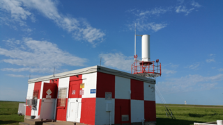
Very High Frequency Omnidirectional Range Station (VOR) is a type of short-range radio navigation system for aircraft, enabling aircraft with a receiving unit to determine its position and stay on course by receiving radio signals transmitted by a network of fixed ground radio beacons. It uses frequencies in the very high frequency (VHF) band from 108.00 to 117.95 MHz. Developed in the United States beginning in 1937 and deployed by 1946, VOR became the standard air navigational system in the world, used by both commercial and general aviation, until supplanted by satellite navigation systems such as GPS in the early 21st century. As such, VOR stations are being gradually decommissioned. In 2000 there were about 3,000 VOR stations operating around the world, including 1,033 in the US, but by 2013 the number in the US had been reduced to 967. The United States is decommissioning approximately half of its VOR stations and other legacy navigation aids as part of a move to performance-based navigation, while still retaining a "Minimum Operational Network" of VOR stations as a backup to GPS. In 2015, the UK planned to reduce the number of stations from 44 to 19 by 2020.

<span class="mw-page-title-main">Gee (navigation)</span> Radio navigation system

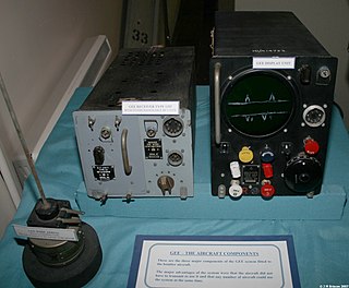
Gee, sometimes written GEE, was a radio navigation system used by the Royal Air Force during World War II. It measured the time delay between two radio signals to produce a fix, with accuracy on the order of a few hundred metres at ranges up to about 350 miles (560 km). It was the first hyperbolic navigation system to be used operationally, entering service with RAF Bomber Command in 1942.

<span class="mw-page-title-main">Distance measuring equipment</span> Radio navigation technology used in aviation

In aviation, distance measuring equipment (DME) is a radio navigation technology that measures the slant range (distance) between an aircraft and a ground station by timing the propagation delay of radio signals in the frequency band between 960 and 1215 megahertz (MHz). Line-of-visibility between the aircraft and ground station is required. An interrogator (airborne) initiates an exchange by transmitting a pulse pair, on an assigned 'channel', to the transponder ground station. The channel assignment specifies the carrier frequency and the spacing between the pulses. After a known delay, the transponder replies by transmitting a pulse pair on a frequency that is offset from the interrogation frequency by 63 MHz and having specified separation.

<span class="mw-page-title-main">Direction finding</span> Measurement of the direction from which a received signal was transmitted

Direction finding (DF), or radio direction finding (RDF), is the use of radio waves to determine the direction to a radio wave source. The source may be a cooperating radio transmitter or may be an inadvertant source, a naturally-occurring radio source, or an illicit or enemy system. Radio direction finding differs from radar in that only the direction is determined by any one receiver; a radar system usually also gives a distance to the object of interest, as well as direction. By triangulation, the location of a radio source can be determined by measuring its direction from two or more locations. Radio direction finding is used in radio navigation for ships and aircraft, to locate emergency transmitters for search and rescue, for tracking wildlife, and to locate illegal or interfering transmitters. During the Second World War, radio direction finding was used by both sides to locate and direct aircraft, surface ships, and submarines.

<span class="mw-page-title-main">Tactical air navigation system</span> Military navigation system

A tactical air navigation system, commonly referred to by the acronym TACAN, is a navigation system used by military aircraft. It provides the user with bearing and distance to a ground or ship-borne station. It is a more accurate version of the VOR/DME system that provides bearing and range information for civil aviation. The DME portion of the TACAN system is available for civil use; at VORTAC facilities where a VOR is combined with a TACAN, civil aircraft can receive VOR/DME readings. Aircraft equipped with TACAN avionics can use this system for en route navigation as well as non-precision approaches to landing fields. The Space Shuttle is one such vehicle that was designed to use TACAN navigation but later upgraded with GPS as a replacement.

Gee-H, sometimes written G-H or GEE-H, was a radio navigation system developed by Britain during World War II to aid RAF Bomber Command. The name refers to the system's use of the earlier Gee equipment, as well as its use of the "H principle" or "twin-range principle" of location determination. Its official name was AMES Type 100.

<span class="mw-page-title-main">Differential GPS</span> Enhancement to the Global Positioning System providing improved accuracy

Differential Global Positioning Systems (DGPSs) supplement and enhance the positional data available from global navigation satellite systems (GNSSs). A DGPS for GPS can increase accuracy by about a thousandfold, from approximately 15 metres (49 ft) to 1–3 centimetres.

<span class="mw-page-title-main">Microwave landing system</span> All-weather, precision radio guidance system

The microwave landing system (MLS) is an all-weather, precision radio guidance system intended to be installed at large airports to assist aircraft in landing, including 'blind landings'. MLS enables an approaching aircraft to determine when it is aligned with the destination runway and on the correct glidepath for a safe landing. MLS was intended to replace or supplement the instrument landing systems (ILS). MLS has a number of operational advantages over ILS, including a wider selection of channels to avoid interference with nearby installations, excellent performance in all weather, a small "footprint" at the airports, and wide vertical and horizontal "capture" angles that allowed approaches from wider areas around the airport.

Pseudo-range multilateration, often simply multilateration (MLAT) when in context, is a technique for determining the position of an unknown point, such as a vehicle, based on measurement of the times of arrival (TOAs) of energy waves traveling between the unknown point and multiple stations at known locations. When the waves are transmitted by the vehicle, MLAT is used for surveillance; when the waves are transmitted by the stations, MLAT is used for navigation. In either case, the stations' clocks are assumed synchronized but the vehicle's clock is not.

<span class="mw-page-title-main">Radio</span> Technology of using radio waves to carry information

Radio is the technology of signaling and communicating using radio waves. Radio waves are electromagnetic waves of frequency between 3 hertz (Hz) and 300 gigahertz (GHz). They are generated by an electronic device called a transmitter connected to an antenna which radiates the waves, and received by another antenna connected to a radio receiver. Radio is widely used in modern technology, in radio communication, radar, radio navigation, remote control, remote sensing, and other applications.

<span class="mw-page-title-main">VOR/DME</span> Aircraft radio navigation station

In radio navigation, a VOR/DME is a radio beacon that combines a VHF omnidirectional range (VOR) with a distance-measuring equipment (DME). The VOR allows the receiver to measure its bearing to or from the beacon, while the DME provides the slant distance between the receiver and the station. Together, the two measurements allow the receiver to compute a position fix.

<span class="mw-page-title-main">Low-frequency radio range</span> Navigation system formerly used by aircraft

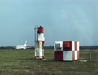
The low-frequency radio range, also known as the four-course radio range, LF/MF four-course radio range, A-N radio range, Adcock radio range, or commonly "the range", was the main navigation system used by aircraft for instrument flying in the 1930s and 1940s, until the advent of the VHF omnidirectional range (VOR), beginning in the late 1940s. It was used for en route navigation as well as instrument approaches and holds.

<span class="mw-page-title-main">Hyperbolic navigation</span> Class of obsolete radio navigation systems

Hyperbolic navigation is a class of radio navigation systems in which a navigation receiver instrument is used to determine location based on the difference in timing of radio waves received from radio navigation beacon transmitters.

Sonne was a radio navigation system developed in Germany during World War II. It was developed from an earlier experimental system known as Elektra, and therefore the system is also known as Elektra-sonnen. When the British learned of the system they started using it as well, under the name Consol, meaning "by the sun".

<span class="mw-page-title-main">LORAN</span> Radio navigation system

LORAN, short for long range navigation, was a hyperbolic radio navigation system developed in the United States during World War II. It was similar to the UK's Gee system but operated at lower frequencies in order to provide an improved range up to 1,500 miles (2,400 km) with an accuracy of tens of miles. It was first used for ship convoys crossing the Atlantic Ocean, and then by long-range patrol aircraft, but found its main use on the ships and aircraft operating in the Pacific theater during World War II.

References

Citations

  1. 1 2 Blanchard 1991, p. 301.
  2. 1 2 3 Blanchard 1991, p. 302.
  3. "Corporation Information". Decca Navigator (Canada) Ltd. Canada Company Directory.
  4. "Decca Marine Canada". Decca Navigator News. September 1976.
  5. "UNITED AIR LINES, INC, DC-8, N 8013U, AND TRANS WORLD AIRLINES, INC., CONSTELLATION 1049A, N 6907C, NEAR STATEN ISLAND, NEW YORK, DECEMBER 16, 1960". Plane and Train Wrecks | Online Collections. Retrieved 17 June 2022.
  6. 1 2 3 Blanchard 1991, p. 303.
  7. 1 2 3 Blanchard 1991, p. 304.
  8. 1 2 3 Blanchard 1991, p. 305.
  9. "Dectra in Iceland", Decca Navigator News, October 1967

Bibliography