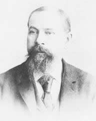
The compression ratio is the ratio between the volume of the cylinder and combustion chamber in an internal combustion engine at their maximum and minimum values.

The diesel engine, named after Rudolf Diesel, is an internal combustion engine in which ignition of the fuel is caused by the elevated temperature of the air in the cylinder due to mechanical compression; thus, the diesel engine is called a compression-ignition engine. This contrasts with engines using spark plug-ignition of the air-fuel mixture, such as a petrol engine or a gas engine.
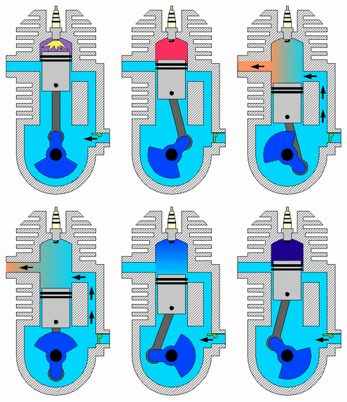
A two-strokeengine is a type of internal combustion engine that completes a power cycle with two strokes of the piston during one power cycle, this power cycle being completed in one revolution of the crankshaft. A four-stroke engine requires four strokes of the piston to complete a power cycle during two crankshaft revolutions. In a two-stroke engine, the end of the combustion stroke and the beginning of the compression stroke happen simultaneously, with the intake and exhaust functions occurring at the same time.
A stratified charge engine describes a certain type of internal combustion engine, usually spark ignition (SI) engine that can be used in trucks, automobiles, portable and stationary equipment. The term "stratified charge" refers to the working fluids and fuel vapors entering the cylinder. Usually the fuel is injected into the cylinder or enters as a fuel rich vapor where a spark or other means are used to initiate ignition where the fuel rich zone interacts with the air to promote complete combustion. A stratified charge can allow for slightly higher compression ratios without "knock," and leaner air/fuel ratio than in conventional internal combustion engines.

A four-strokeengine is an internal combustion (IC) engine in which the piston completes four separate strokes while turning the crankshaft. A stroke refers to the full travel of the piston along the cylinder, in either direction. The four separate strokes are termed:
- Intake: Also known as induction or suction. This stroke of the piston begins at top dead center (T.D.C.) and ends at bottom dead center (B.D.C.). In this stroke the intake valve must be in the open position while the piston pulls an air-fuel mixture into the cylinder by producing a partial vacuum in the cylinder through its downward motion.
- Compression: This stroke begins at B.D.C, or just at the end of the suction stroke, and ends at T.D.C. In this stroke the piston compresses the air-fuel mixture in preparation for ignition during the power stroke (below). Both the intake and exhaust valves are closed during this stage.
- Combustion: Also known as power or ignition. This is the start of the second revolution of the four stroke cycle. At this point the crankshaft has completed a full 360 degree revolution. While the piston is at T.D.C. the compressed air-fuel mixture is ignited by a spark plug or by heat generated by high compression, forcefully returning the piston to B.D.C. This stroke produces mechanical work from the engine to turn the crankshaft.
- Exhaust: Also known as outlet. During the exhaust stroke, the piston, once again, returns from B.D.C. to T.D.C. while the exhaust valve is open. This action expels the spent air-fuel mixture through the exhaust port.

Nicolaus August Otto was a German engineer who successfully developed the compressed charge internal combustion engine which ran on petroleum gas and led to the modern internal combustion engine. The Association of German Engineers (VDI) created DIN standard 1940 which says "Otto Engine: internal combustion engine in which the ignition of the compressed fuel-air mixture is initiated by a timed spark", which has been applied to all engines of this type since.

The Brayton cycle is a thermodynamic cycle that describes the operation of certain heat engines that have air or some other gas as their working fluid. The original Brayton Ready Motor used a piston compressor and piston expander, but modern gas turbine engines and airbreathing jet engines also follow the Brayton cycle. Although the cycle is usually run as an open system, it is conventionally assumed for the purposes of thermodynamic analysis that the exhaust gases are reused in the intake, enabling analysis as a closed system.
William Hall Barnett is described as a 'founder' in his 1836 patent, and an 'ironfounder' in his 1838 patent, and later as an engineer and gas engineer, working in Brighton, UK. He worked for many years for the Brighton and Hove General Gas Company. He was born in Bradford and died in Brighton.
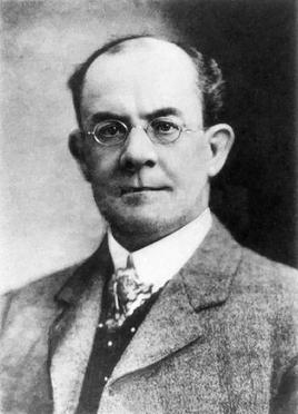
Herbert Akroyd-Stuart was an English inventor who is noted for his invention of the hot bulb engine, or heavy oil engine.
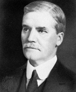
Sir Dugald Clerk KBE, LLD FRS was a Scottish engineer who designed the world's first successful two-stroke engine in 1878 and patented it in England in 1881. He was a graduate of Anderson's University in Glasgow, and Yorkshire College, Leeds. He formed the intellectual property firm with George Croydon Marks, called Marks & Clerk. He was knighted on 24 August 1917.
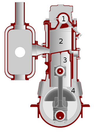
The hot-bulb engine, also known as a semi-diesel, is a type of internal combustion engine in which fuel ignites by coming in contact with a red-hot metal surface inside a bulb, followed by the introduction of air (oxygen) compressed into the hot-bulb chamber by the rising piston. There is some ignition when the fuel is introduced, but it quickly uses up the available oxygen in the bulb. Vigorous ignition takes place only when sufficient oxygen is supplied to the hot-bulb chamber on the compression stroke of the engine.
The term six-stroke engine has been applied to a number of alternative internal combustion engine designs that attempt to improve on traditional two-stroke and four-stroke engines. Claimed advantages may include increased fuel efficiency, reduced mechanical complexity, and/or reduced emissions. These engines can be divided into two groups based on the number of pistons that contribute to the six strokes.
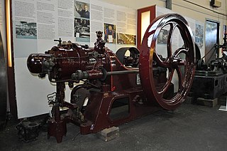
The Hornsby-Akroyd oil engine, named after its inventor Herbert Akroyd Stuart and the manufacturer Richard Hornsby & Sons, was the first successful design of an internal combustion engine using heavy oil as a fuel. It was the first to use a separate vapourising combustion chamber and is the forerunner of all hot-bulb engines, which are considered predecessors of the similar Diesel engine, developed a few years later.
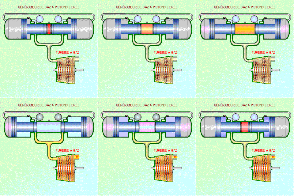
A free-piston engine is a linear, 'crankless' internal combustion engine, in which the piston motion is not controlled by a crankshaft but determined by the interaction of forces from the combustion chamber gases, a rebound device and a load device.
Internal combustion engines date back to between the 10th and 13th centuries, when the first rocket engines were invented in China. Following the first commercial steam engine in 1698, various efforts were made during the 18th century to develop equivalent internal combustion engines. In 1791, the English inventor John Barber patented a gas turbine. In 1794, Thomas Mead patented a gas engine. Also in 1794, Robert Street patented an internal-combustion engine, which was also the first to use liquid fuel (petroleum) and built an engine around that time. In 1798, John Stevens designed the first American internal combustion engine. In 1807, French engineers Nicéphore and Claude Niépce ran a prototype internal combustion engine, using controlled dust explosions, the Pyréolophore. This engine powered a boat on the river in France. The same year, the Swiss engineer François Isaac de Rivaz built and patented a hydrogen and oxygen-powered internal-combustion engine. Fitted to a crude four-wheeled wagon, François Isaac de Rivaz first drove it 100 metres in 1813, thus making history as the first car-like vehicle known to have been powered by an internal-combustion engine.
Internal combustion engines come in a wide variety of types, but have certain family resemblances, and thus share many common types of components.
Lemuel Wellman Wright was an inventor who was active in the early 19th century. He was born in Plainfield, New Hampshire, and educated at Haverhill, New Hampshire. He then took a raft down the Connecticut River to Middletown, Connecticut, where he learned the clockmaker trade. He opened a clock-making shop in New York City before accepting a position to introduce American textile manufacturing machinery to the United Kingdom of Great Britain and Ireland. He remained in the British Isles from 1816 until returning to New York in 1857. The name Lemuel Wellman Wright is recorded in the British patent index for the patents listed below, but some texts use Lemuel Willman Wright to refer to the author of the same patents. There are contemporary references to an American from Massachusetts, Lemuel William Wright, who patented machinery and created a factory to make pins in London. The patent subject index lists the author of a patent for making pins in 1824 as Lemuel Wellman Wright, and has no other similar names recorded related to pins, so unless the patent office publication is in error, all these references appear to be to the same inventor.
Pierre Hugon is mainly known through his contribution to the early internal combustion engine, especially the "Hugon" engine, which was the second internal combustion engine to go into commercial production - and was a stationary engine along similar lines to the earlier "Lenoir" engine. According to various patents and other entries Pierre Hugon is variously described as a "Civil Engineer", and also as "directeur de la Compagnie du Gaz de Paris". In 1866 the London Gazette informs us that he is resident in Paris at 56 Rue de l'Orient, and in his US patent of 1874 he is still listed as a resident of Paris.

An internal combustion engine is a heat engine in which the combustion of a fuel occurs with an oxidizer in a combustion chamber that is an integral part of the working fluid flow circuit. In an internal combustion engine, the expansion of the high-temperature and high-pressure gases produced by combustion applies direct force to some component of the engine. The force is typically applied to pistons, turbine blades, a rotor, or a nozzle. This force moves the component over a distance, transforming chemical energy into kinetic energy which is used to propel, move or power whatever the engine is attached to.

The five-stroke engine is a compound internal combustion engine patented by Gerhard Schmitz in 2000. Schmitz's concept is being developed by Ilmor Engineering. Ilmor's prototype is an internal combustion engine that uses a solid cylinder block with electric motors driving the oil and water cooling pumps. The prototype uses two overhead camshafts with standard poppet valves. The five-stroke prototype engine is turbocharged. The goal of the five-stroke engine is to have higher efficiency with lower fuel use. In order to increase efficiency, a secondary cylinder is added as an expansion processor to extract more energy from the fuel.
