
A boiling water reactor (BWR) is a type of light water nuclear reactor used for the generation of electrical power. It is the second most common type of electricity-generating nuclear reactor after the pressurized water reactor (PWR), which is also a type of light water nuclear reactor. The main difference between a BWR and PWR is that in a BWR, the reactor core heats water, which turns to steam and then drives a steam turbine. In a PWR, the reactor core heats water, which does not boil. This hot water then exchanges heat with a lower pressure water system, which turns to steam and drives the turbine. The BWR was developed by the Argonne National Laboratory and General Electric (GE) in the mid-1950s. The main present manufacturer is GE Hitachi Nuclear Energy, which specializes in the design and construction of this type of reactor.
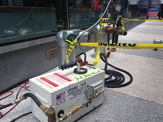
A hydrostatic test is a way in which pressure vessels such as pipelines, plumbing, gas cylinders, boilers and fuel tanks can be tested for strength and leaks. The test involves filling the vessel or pipe system with a liquid, usually water, which may be dyed to aid in visual leak detection, and pressurization of the vessel to the specified test pressure. Pressure tightness can be tested by shutting off the supply valve and observing whether there is a pressure loss. The location of a leak can be visually identified more easily if the water contains a colorant. Strength is usually tested by measuring permanent deformation of the container. Hydrostatic testing is the most common method employed for testing pipes and pressure vessels. Using this test helps maintain safety standards and durability of a vessel over time. Newly manufactured pieces are initially qualified using the hydrostatic test. They are then re-qualified at regular intervals using the proof pressure test which is also called the modified hydrostatic test. Testing of pressure vessels for transport and storage of gases is very important because such containers can explode if they fail under pressure.

A relief valve or pressure relief valve (PRV) is a type of safety valve used to control or limit the pressure in a system; pressure might otherwise build up and create a process upset, instrument or equipment failure, or fire. The pressure is relieved by allowing the pressurised fluid to flow from an auxiliary passage out of the system. The relief valve is designed or set to open at a predetermined set pressure to protect pressure vessels and other equipment from being subjected to pressures that exceed their design limits. When the set pressure is exceeded, the relief valve becomes the "path of least resistance" as the valve is forced open and a portion of the fluid is diverted through the auxiliary route. The diverted fluid is usually routed through a piping system known as a flare header or relief header to a central, elevated gas flare where it is usually burned and the resulting combustion gases are released to the atmosphere. As the fluid is diverted, the pressure inside the vessel will stop rising. Once it reaches the valve's reseating pressure, the valve will close. The blowdown is usually stated as a percentage of set pressure and refers to how much the pressure needs to drop before the valve reseats. The blowdown can vary from roughly 2–20%, and some valves have adjustable blowdowns.
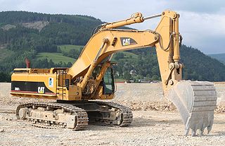
Hydraulic machines are machinery and tools that use liquid fluid power to do simple work, operated by the use of hydraulics, where a liquid is the powering medium. In heavy equipment and other types of machine, hydraulic fluid is transmitted throughout the machine to various hydraulic motors and hydraulic cylinders and becomes pressurised according to the resistance present. The fluid is controlled directly or automatically by control valves and distributed through hoses and tubes.

A chemical plant is an industrial process plant that manufactures chemicals, usually on a large scale. The general objective of a chemical plant is to create new material wealth via the chemical or biological transformation and or separation of materials. Chemical plants use specialized equipment, units, and technology in the manufacturing process. Other kinds of plants, such as polymer, pharmaceutical, food, and some beverage production facilities, power plants, oil refineries or other refineries, natural gas processing and biochemical plants, water and wastewater treatment, and pollution control equipment use many technologies that have similarities to chemical plant technology such as fluid systems and chemical reactor systems. Some would consider an oil refinery or a pharmaceutical or polymer manufacturer to be effectively a chemical plant.

A containment building, in its most common usage, is a reinforced steel or lead structure enclosing a nuclear reactor. It is designed, in any emergency, to contain the escape of radioactive steam or gas to a maximum pressure in the range of 275 to 550 kPa. The containment is the fourth and final barrier to radioactive release, the first being the fuel ceramic itself, the second being the metal fuel cladding tubes, the third being the reactor vessel and coolant system.
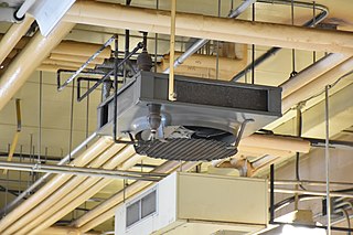
Hydronics is the use of a liquid heat-transfer medium in heating and cooling systems. The working fluid is typically water, glycol, or mineral oil. Some of the oldest and most common examples are steam and hot-water radiators. Historically, in large-scale commercial buildings such as high-rise and campus facilities, a hydronic system may include both a chilled and a heated water loop, to provide for both heating and air conditioning. Chillers and cooling towers are used either separately or together as means to provide water cooling, while boilers heat water. A recent innovation is the chiller boiler system, which provides an efficient form of HVAC for homes and smaller commercial spaces.
Hydropneumatic devices such as hydropneumatic accumulators or pulsation dampeners are devices which prevent, but do not absorb, alleviate, arrest, attenuate, or suppress a shock that already exists, meaning that these devices prevent the creation of a shock wave at an otherwise earlier stage. These can include pulsation dampeners, hydropneumatic accumulators, water hammer preventers, water hammer arrestors, and other things.

A wellhead is the component at the surface of an oil or gas well that provides the structural and pressure-containing interface for the drilling and production equipment.
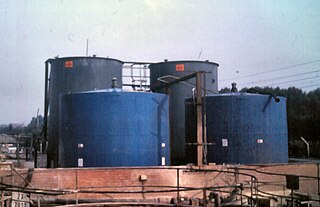
Bunding, also called a bund wall, is a constructed retaining wall around storage "where potentially polluting substances are handled, processed or stored, for the purposes of containing any unintended escape of material from that area until such time as a remedial action can be taken."
Pressure drop is defined as the difference in total pressure between two points of a fluid carrying network.
A pressure drop occurs when frictional forces, caused by the resistance to flow, act on a fluid as it flows through the tube. The main determinants of resistance to fluid flow are fluid velocity through the pipe and fluid viscosity. Pressure drop increases proportionally to the frictional shear forces within the piping network. A piping network containing a high relative roughness rating as well as many pipe fittings and joints, tube convergence, divergence, turns, surface roughness, and other physical properties will affect the pressure drop. High flow velocities and/or high fluid viscosities result in a larger pressure drop across a section of pipe or a valve or elbow. Low velocity will result in lower or no pressure drop. The fluid may also be biphasic as in pneumatic conveying with a gas and a solid, in this case, the friction of the solid must also be taken into consideration for calculating the pressure drop

A fitting is used in pipe systems to connect the straight pipe or tubing sections, adapt to different sizes or shapes and for other purposes, such as regulating fluid flow. "Plumbing" is generally used to describe the conveyance of water, gas, or liquid waste in domestic or commercial environments; "piping" is often used to describe the high-performance conveyance of fluids in specialized applications. "Tubing" is sometimes used for lighter-weight piping, especially that flexible enough to be supplied in coiled form.

A well intervention, or well work, is any operation carried out on an oil or gas well during, or at the end of, its productive life that alters the state of the well or well geometry, provides well diagnostics, or manages the production of the well.
A downhole safety valve refers to a component on an oil and gas well, which acts as a failsafe to prevent the uncontrolled release of reservoir fluids in the event of a worst-case-scenario surface disaster. It is almost always installed as a vital component on the completion.
The term separator in oilfield terminology designates a pressure vessel used for separating well fluids produced from oil and gas wells into gaseous and liquid components. A separator for petroleum production is a large vessel designed to separate production fluids into their constituent components of oil, gas and water. A separating vessel may be referred to in the following ways: Oil and gas separator, Separator, Stage separator, Trap, Knockout vessel, Flash chamber, Expansion separator or expansion vessel, Scrubber, Filter. These separating vessels are normally used on a producing lease or platform near the wellhead, manifold, or tank battery to separate fluids produced from oil and gas wells into oil and gas or liquid and gas. An oil and gas separator generally includes the following essential components and features:

Well completion is the process of making a well ready for production. This principally involves preparing the bottom of the hole to the required specifications, running in the production tubing and its associated down hole tools as well as perforating and stimulating as required. Sometimes, the process of running in and cementing the casing is also included. After a well has been drilled, should the drilling fluids be removed, the well would eventually close in upon itself. Casing ensures that this will not happen while also protecting the wellstream from outside incumbents, like water or sand.

An industrial safety system is a countermeasure crucial in any hazardous plants such as oil and gas plants and nuclear plants. They are used to protect human, industrial plant, and the environment in case of the process going beyond the allowed control margins.
Instrumentation is used to monitor and control the process plant in the oil, gas and petrochemical industries. Instrumentation comprises sensor elements, signal transmitters, controllers, indicators and alarms, actuated valves, logic circuits and operator interfaces.
Boiling water reactor safety systems are nuclear safety systems constructed within boiling water reactors in order to prevent or mitigate environmental and health hazards in the event of accident or natural disaster.
