
An inductor, also called a coil, choke, or reactor, is a passive two-terminal electrical component that stores energy in a magnetic field when electric current flows through it. An inductor typically consists of an insulated wire wound into a coil.

The characteristic impedance or surge impedance (usually written Z0) of a uniform transmission line is the ratio of the amplitudes of voltage and current of a single wave propagating along the line; that is, a wave travelling in one direction in the absence of reflections in the other direction. Alternatively, and equivalently, it can be defined as the input impedance of a transmission line when its length is infinite. Characteristic impedance is determined by the geometry and materials of the transmission line and, for a uniform line, is not dependent on its length. The SI unit of characteristic impedance is the ohm.

In electrical engineering, a transmission line is a specialized cable or other structure designed to conduct electromagnetic waves in a contained manner. The term applies when the conductors are long enough that the wave nature of the transmission must be taken into account. This applies especially to radio-frequency engineering because the short wavelengths mean that wave phenomena arise over very short distances. However, the theory of transmission lines was historically developed to explain phenomena on very long telegraph lines, especially submarine telegraph cables.

Coaxial cable, or coax, is a type of electrical cable consisting of an inner conductor surrounded by a concentric conducting shield, with the two separated by a dielectric ; many coaxial cables also have a protective outer sheath or jacket. The term coaxial refers to the inner conductor and the outer shield sharing a geometric axis.

Ohm's law states that the current through a conductor between two points is directly proportional to the voltage across the two points. Introducing the constant of proportionality, the resistance, one arrives at the three mathematical equations used to describe this relationship:

The electrical resistance of an object is a measure of its opposition to the flow of electric current. Its reciprocal quantity is electrical conductance, measuring the ease with which an electric current passes. Electrical resistance shares some conceptual parallels with mechanical friction. The SI unit of electrical resistance is the ohm, while electrical conductance is measured in siemens (S).

Electromagnetic or magnetic induction is the production of an electromotive force (emf) across an electrical conductor in a changing magnetic field.
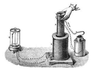
An electromagnet is a type of magnet in which the magnetic field is produced by an electric current. Electromagnets usually consist of wire wound into a coil. A current through the wire creates a magnetic field which is concentrated in the hole in the center of the coil. The magnetic field disappears when the current is turned off. The wire turns are often wound around a magnetic core made from a ferromagnetic or ferrimagnetic material such as iron; the magnetic core concentrates the magnetic flux and makes a more powerful magnet.
In electrical circuits, reactance is the opposition presented to alternating current by inductance and capacitance. Along with resistance, it is one of two elements of impedance; however, while both elements involve transfer of electrical energy, no dissipation of electrical energy as heat occurs in reactance; instead, the reactance stores energy until a quarter-cycle later when the energy is returned to the circuit. Greater reactance gives smaller current for the same applied voltage.
Inductance is the tendency of an electrical conductor to oppose a change in the electric current flowing through it. The electric current produces a magnetic field around the conductor. The magnetic field strength depends on the magnitude of the electric current, and follows any changes in the magnitude of the current. From Faraday's law of induction, any change in magnetic field through a circuit induces an electromotive force (EMF) (voltage) in the conductors, a process known as electromagnetic induction. This induced voltage created by the changing current has the effect of opposing the change in current. This is stated by Lenz's law, and the voltage is called back EMF.

A solenoid is a type of electromagnet formed by a helical coil of wire whose length is substantially greater than its diameter, which generates a controlled magnetic field. The coil can produce a uniform magnetic field in a volume of space when an electric current is passed through it.
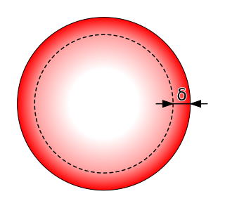
In electromagnetism, skin effect is the tendency of an alternating electric current (AC) to become distributed within a conductor such that the current density is largest near the surface of the conductor and decreases exponentially with greater depths in the conductor. The electric current flows mainly at the "skin" of the conductor, between the outer surface and a level called the skin depth. Skin depth depends on the frequency of the alternating current; as frequency increases, current flow becomes more concentrated near the surface, resulting in less skin depth. Skin effect reduces the effective cross-section of the conductor and thus increases its effective resistance. It is caused by opposing eddy currents induced by the changing magnetic field resulting from the alternating current. At 60 Hz in copper, skin depth is about 8.5 mm. At high frequencies skin depth becomes much smaller.
Joule heating, also known as resistive, resistance, or Ohmic heating, is the process by which the passage of an electric current through a conductor produces heat.
Faraday's law of induction is a basic law of electromagnetism predicting how a magnetic field will interact with an electric circuit to produce an electromotive force (emf)—a phenomenon known as electromagnetic induction. It is the fundamental operating principle of transformers, inductors, and many types of electric motors, generators and solenoids.
Permeance, in general, is the degree to which a material admits a flow of matter or energy. Permeance is usually represented by a curly capital P: .

In electronics, a Lecher line or Lecher wires is a pair of parallel wires or rods that were used to measure the wavelength of radio waves, mainly at VHF, UHF and microwave frequencies. They form a short length of balanced transmission line. When attached to a source of radio-frequency power such as a radio transmitter, the radio waves form standing waves along their length. By sliding a conductive bar that bridges the two wires along their length, the length of the waves can be physically measured. Austrian physicist Ernst Lecher, improving on techniques used by Oliver Lodge and Heinrich Hertz, developed this method of measuring wavelength around 1888. Lecher lines were used as frequency measuring devices until frequency counters became available after World War 2. They were also used as components, often called "resonant stubs", in VHF, UHF and microwave radio equipment such as transmitters, radar sets, and television sets, serving as tank circuits, filters, and impedance-matching devices. They are used at frequencies between HF/VHF, where lumped components are used, and UHF/SHF, where resonant cavities are more practical.
The telegrapher's equations are a set of two coupled, linear equations that predict the voltage and current distributions on a linear electrical transmission line. The equations are important because they allow transmission lines to be analyzed using circuit theory. The equations and their solutions are applicable from 0 Hz to frequencies at which the transmission line structure can support higher order non-TEM modes. The equations can be expressed in both the time domain and the frequency domain. In the time domain the independent variables are distance and time. The resulting time domain equations are partial differential equations of both time and distance. In the frequency domain the independent variables are distance and either frequency, or complex frequency, The frequency domain variables can be taken as the Laplace transform or Fourier transform of the time domain variables or they can be taken to be phasors. The resulting frequency domain equations are ordinary differential equations of distance. An advantage of the frequency domain approach is that differential operators in the time domain become algebraic operations in frequency domain.

Mersenne's laws are laws describing the frequency of oscillation of a stretched string or monochord, useful in musical tuning and musical instrument construction.

In electromagnetics, proximity effect is a redistribution of electric current occurring in nearby parallel electrical conductors carrying alternating current (AC), caused by magnetic effects. In adjacent conductors carrying AC current in the same direction, it causes the current in the conductor to concentrate on the side away from the nearby conductor. In conductors carrying AC current in opposite directions, it causes the current in the conductor to concentrate on the side adjacent to the nearby conductor. Proximity effect is caused by eddy currents induced within a conductor by the time-varying magnetic field of the other conductor, by electromagnetic induction. For example, in a coil of wire carrying alternating current with multiple turns of wire lying next to each other, the current in each wire will be concentrated in a strip on each side of the wire facing away from the adjacent wires. This "current crowding" effect causes the current to occupy a smaller effective cross-sectional area of the conductor, increasing current density and AC electrical resistance of the conductor. The concentration of current on the side of the conductor gets larger with increasing frequency, so proximity effect causes adjacent wires carrying the same current to have more resistance at higher frequencies.
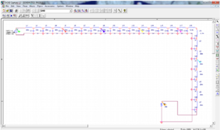
Performance modelling is the abstraction of a real system into a simplified representation to enable the prediction of performance. The creation of a model can provide insight into how a proposed or actual system will or does work. This can, however, point towards different things to people belonging to different fields of work.


