Elmore delay [1] is a simple approximation to the delay through an RC network in an electronic system. It is often used in applications such as logic synthesis, delay calculation, static timing analysis, placement and routing, since it is simple to compute (especially in tree structured networks, which are the vast majority of signal nets within ICs) and is reasonably accurate. Even where it is not accurate, it is usually faithful, in the sense that reducing the Elmore delay will almost always reduce the true delay, so it is still useful in optimization.
In electronics, logic synthesis is a process by which an abstract specification of desired circuit behavior, typically at register transfer level (RTL), is turned into a design implementation in terms of logic gates, typically by a computer program called a synthesis tool. Common examples of this process include synthesis of designs specified in hardware description languages, including VHDL and Verilog. Some synthesis tools generate bitstreams for programmable logic devices such as PALs or FPGAs, while others target the creation of ASICs. Logic synthesis is one aspect of electronic design automation.
Delay calculation is the term used in integrated circuit design for the calculation of the gate delay of a single logic gate and the wires attached to it. By contrast, static timing analysis computes the delays of entire paths, using delay calculation to determine the delay of each gate and wire.
Static timing analysis (STA) is a simulation method of computing the expected timing of a digital circuit without requiring a simulation of the full circuit.
Elmore delay can be thought of in several ways, all mathematically identical.
- For tree structured networks, find the delay through each segment as the R (electrical resistance) times the downstream C (electrical capacitance). Sum the delays from the root to the sink.
- Assume the output is a simple exponential, and find the exponential that has the same integral as the true response. This is also equivalent to moment matching with one moment, since the first moment is a pure exponential.
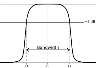
- Find a one pole approximation to the true frequency response. This is a first-order Padé approximation.

Capacitance is the ratio of the change in an electric charge in a system to the corresponding change in its electric potential. There are two closely related notions of capacitance: self capacitance and mutual capacitance. Any object that can be electrically charged exhibits self capacitance. A material with a large self capacitance holds more electric charge at a given voltage than one with low capacitance. The notion of mutual capacitance is particularly important for understanding the operations of the capacitor, one of the three elementary linear electronic components.
In packet switching networks, traffic flow, packet flow or network flow is a sequence of packets from a source computer to a destination, which may be another host, a multicast group, or a broadcast domain. RFC 2722 defines traffic flow as "an artificial logical equivalent to a call or connection." RFC 3697 defines traffic flow as "a sequence of packets sent from a particular source to a particular unicast, anycast, or multicast destination that the source desires to label as a flow. A flow could consist of all packets in a specific transport connection or a media stream. However, a flow is not necessarily 1:1 mapped to a transport connection." Flow is also defined in RFC 3917 as "a set of IP packets passing an observation point in the network during a certain time interval."

In mathematics a Padé approximant is the 'best' approximation of a function by a rational function of given order – under this technique, the approximant's power series agrees with the power series of the function it is approximating. The technique was developed around 1890 by Henri Padé, but goes back to Georg Frobenius who introduced the idea and investigated the features of rational approximations of power series.
There are many extensions to Elmore delay. It can be extended to upper and lower bounds, [2] to include inductance as well as R and C, to be more accurate (higher order approximations) [3] and so on. See delay calculation for more details and references.
In electromagnetism and electronics, inductance describes the tendency of an electrical conductor, such as coil, to oppose a change in the electric current through it. When an electric current flows through a conductor, it creates a magnetic field around that conductor. A changing current, in turn, creates a changing magnetic field. From Faraday's law of induction, any change in total magnetic field through a circuit induces an electromotive force (voltage) across that circuit, a phenomenon known as electromagnetic induction. From Lenz's law, this induced voltage, or "back EMF" in a circuit, will be in a direction so as to oppose the change in current which created it. So changes in current through a conductor will react back on the conductor itself through its magnetic field, creating a reverse voltage which will oppose any change to the current. Inductance, , is defined as the ratio between this induced voltage, , and the rate of change of the current in the circuit.