
A plotter produces vector graphics drawings. Plotters draw lines on paper using a pen, or in some applications, use a knife to cut a material like vinyl or leather. In the latter case, they are sometimes known as a cutting plotter.
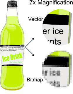
Vector graphics are computer graphics images that are defined in terms of points on a Cartesian plane, which are connected by lines and curves to form polygons and other shapes. Vector graphics have the unique advantage over raster graphics in that the points, lines, and curves may be scaled up or down to any resolution with no aliasing. The points determine the direction of the vector path; each path may have various properties including values for stroke color, shape, curve, thickness, and fill.

A cam is a rotating or sliding piece in a mechanical linkage used especially in transforming rotary motion into linear motion. It is often a part of a rotating wheel or shaft that strikes a lever at one or more points on its circular path. The cam can be a simple tooth, as is used to deliver pulses of power to a steam hammer, for example, or an eccentric disc or other shape that produces a smooth reciprocating motion in the follower, which is a lever making contact with the cam. A cam timer is similar, and were widely used for electric machine control before the advent of inexpensive electronics, microcontrollers, integrated circuits, programmable logic controllers and digital control.
Computer-aided manufacturing (CAM) also known as Computer-aided Modeling or Computer-aided Machining is the use of software to control machine tools and related ones in the manufacturing of work pieces. This is not the only definition for CAM, but it is the most common; CAM may also refer to the use of a computer to assist in all operations of a manufacturing plant, including planning, management, transportation and storage. Its primary purpose is to create a faster production process and components and tooling with more precise dimensions and material consistency, which in some cases, uses only the required amount of raw material, while simultaneously reducing energy consumption. CAM is now a system used in schools and lower educational purposes. CAM is a subsequent computer-aided process after computer-aided design (CAD) and sometimes computer-aided engineering (CAE), as the model generated in CAD and verified in CAE can be input into CAM software, which then controls the machine tool. CAM is used in many schools alongside Computer-Aided Design (CAD) to create objects.

A shaper is a type of machine tool that uses linear relative motion between the workpiece and a single-point cutting tool to machine a linear toolpath. Its cut is analogous to that of a lathe, except that it is (archetypally) linear instead of helical.

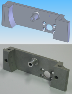
Ray casting is the methodological basis for 3-D CAD/CAM solid modeling and image rendering. It is essentially the same as ray tracing for computer graphics where virtual light rays are "cast" or "traced" on their path from the focal point of a camera through each pixel in the camera sensor to determine what is visible along the ray in the 3-D scene. The term "Ray Casting" was introduced by Scott Roth while at the General Motors Research Labs from 1978-1980. His paper, "Ray Casting for Modeling Solids", describes modeled solid objects by combining primitive solids, such as blocks and cylinders, using the set operators union (+), intersection (&), and difference (-). The general idea of using these binary operators for solid modeling is largely due to Voelcker and Requicha's geometric modelling group at the University of Rochester. See Solid modeling for a broad overview of solid modeling methods. This figure on the right shows a U-Joint modeled from cylinders and blocks in a binary tree using Roth's ray casting system, circa 1979.
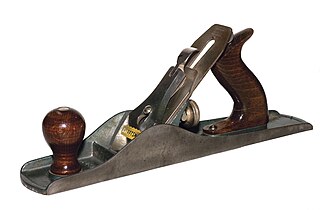
A hand plane is a tool for shaping wood using muscle power to force the cutting blade over the wood surface. Some rotary power planers are motorized power tools used for the same types of larger tasks, but are unsuitable for fine scale planing where a miniature hand plane is used.

Laser engraving is the practice of using lasers to engrave an object. Laser marking, on the other hand, is a broader category of methods to leave marks on an object, which also includes color change due to chemical/molecular alteration, charring, foaming, melting, ablation, and more. The technique does not involve the use of inks, nor does it involve tool bits which contact the engraving surface and wear out, giving it an advantage over alternative engraving or marking technologies where inks or bit heads have to be replaced regularly.
Broaching is a machining process that uses a toothed tool, called a broach, to remove material. There are two main types of broaching: linear and rotary. In linear broaching, which is the more common process, the broach is run linearly against a surface of the workpiece to effect the cut. Linear broaches are used in a broaching machine, which is also sometimes shortened to broach. In rotary broaching, the broach is rotated and pressed into the workpiece to cut an axisymmetric shape. A rotary broach is used in a lathe or screw machine. In both processes the cut is performed in one pass of the broach, which makes it very efficient.
G-code is the most widely used computer numerical control (CNC) programming language. It is used mainly in computer-aided manufacturing to control automated machine tools, and has many variants.

The phrase speeds and feeds or feeds and speeds refers to two separate velocities in machine tool practice, cutting speed and feed rate. They are often considered as a pair because of their combined effect on the cutting process. Each, however, can also be considered and analyzed in its own right.

A grinding wheel is a wheel composed of an abrasive compound and used for various grinding and abrasive machining operations. Such wheels are used in grinding machines.

The elevation of a geographic location is its height above or below a fixed reference point, most commonly a reference geoid, a mathematical model of the Earth's sea level as an equipotential gravitational surface . The term elevation is mainly used when referring to points on the Earth's surface, while altitude or geopotential height is used for points above the surface, such as an aircraft in flight or a spacecraft in orbit, and depth is used for points below the surface.

A tool and cutter grinder is used to sharpen milling cutters and tool bits along with a host of other cutting tools.
Milling cutters are cutting tools typically used in milling machines or machining centres to perform milling operations. They remove material by their movement within the machine or directly from the cutter's shape.

A thickness planer is a woodworking machine to trim boards to a consistent thickness throughout their length and flat on both surfaces.
A cutter location (CLData) refers to the position which a CNC milling machine has been instructed to hold a milling cutter by the instructions in the program.

Pencil milling is a cleanup toolpath generated by computer-aided manufacturing (CAM) programs to machine internal corners and fillets with smaller radius tools to remove the remaining material that are inaccessible with larger tools used for previous roughing, semi-finishing, and finishing toolpaths. The name comes from the way that a pencil could naturally be drawn along these corners. It is sometimes called a rolling ball toolpath.

WorkNC is a Computer aided manufacturing (CAM) software developed by Sescoi for multi-axis machining.

Milling is the process of machining using rotary cutters to remove material by advancing a cutter into a work piece. This may be done varying direction on one or several axes, cutter head speed, and pressure. Milling covers a wide variety of different operations and machines, on scales from small individual parts to large, heavy-duty gang milling operations. It is one of the most commonly used processes for machining custom parts to precise tolerances.