Rifleman's rule

Last updated
Figure 1: Illustration of the Shooting Scenario. RiflemansRule.svg
Figure 1: Illustration of the Shooting Scenario.

Rifleman's rule is a "rule of thumb" that allows a rifleman to accurately fire a rifle that has been calibrated for horizontal targets at uphill or downhill targets. The rule says that only the horizontal range should be considered when adjusting a sight or performing hold-over in order to account for bullet drop. Typically, the range of an elevated target is considered in terms of the slant range, incorporating both the horizontal distance and the elevation distance (possibly negative, i.e. downhill), as when a rangefinder is used to determine the distance to target. The slant range is not compatible with standard ballistics tables for estimating bullet drop.

Contents

The Rifleman's rule provides an estimate of the horizontal range for engaging a target at a known slant range (the uphill or downhill distance from the rifle). For a bullet to strike a target at a slant range of and an incline of , the rifle sight must be adjusted as if the shooter were aiming at a horizontal target at a range of . Figure 1 illustrates the shooting scenario. The rule holds for inclined and declined shooting (all angles measured with respect to horizontal). Very precise computer modeling and empirical evidence suggests that the rule does appear to work with reasonable accuracy in air and with both bullets and arrows.

Background

Definitions

There is a device that is mounted on the rifle called a sight. While there are many forms of rifle sight, they all permit the shooter to set the angle between the bore of the rifle and the line of sight (LOS) to the target. Figure 2 illustrates the relationship between the LOS and bore angle.

Figure 2: Illustration of a Rifle Showing Line of Sight and Bore Angle. Figure 2- Illustration of a Rifle Showing Line of Sight and Bore Angle.jpg
Figure 2: Illustration of a Rifle Showing Line of Sight and Bore Angle.

This relationship between the LOS to the target and the bore angle is determined through a process called "zeroing." The bore angle is set to ensure that a bullet on a parabolic trajectory will intersect the LOS to the target at a specific range. A properly adjusted rifle barrel and sight are said to be "zeroed." Figure 3 illustrates how the LOS, bullet trajectory, and range () are related.

Figure 3: Illustration of a Rifle Showing the LOS and Bore Angle. TargetShooting3.gif
Figure 3: Illustration of a Rifle Showing the LOS and Bore Angle.

Procedure

In general, the shooter will have a table of bullet heights with respect to the LOS versus horizontal distance. Historically, this table has been referred to as a "drop table." The drop table can be generated empirically using data taken by the shooter at a rifle range; calculated using a ballistic simulator; or is provided by the rifle/cartridge manufacturer. The drop values are measured or calculated assuming the rifle has been zeroed at a specific range. The bullet will have a drop value of zero at the zero range. Table 1 gives a typical example of a drop table for a rifle zeroed at 100 meters.

Table 1: Example Bullet Drop Table

Range (meters)0100200300400500
Bullet Height (cm)-1.500.0-2.9-11.0-25.2-46.4

If the shooter is engaging a target on an incline and has a properly zeroed rifle, the shooter goes through the following procedure:

  1. Determine the slant range to the target (measurement can be performed using various forms of range finders, e.g. laser rangefinder)
  2. Determine the elevation angle of the target (measurement can be made using various devices, e.g. sight attached unit)
  3. Apply the "rifleman's rule" to determine the equivalent horizontal range ()
  4. Use the bullet drop table to determine the bullet drop over that equivalent horizontal range (interpolation is likely to be required)
  5. Compute the bore angle correction that is to be applied to the sight. The correction is computed using the equation (in radians).
  6. Adjust the bore angle by the angle correction.

Example

Assume a rifle is being fired that shoots with the bullet drop table given in Table 1. This means that the rifle sight setting for any range from 0 to 500 meters is available. The sight adjustment procedure can be followed step-by-step.

1. Determine the slant range to the target.

Assume that a range finder is available that determines that the target is exactly 300 meters distance.

2. Determine the elevation angle of the target.

Assume that an angle measurement tool is used that measures the target to be at an angle of with respect to horizontal.

3. Apply the rifleman's rule to determine the equivalent horizontal range.

4. Use the bullet drop table to determine the bullet drop over that equivalent horizontal range.

Linear interpolation can be used to estimate the bullet drop as follows:

5. Compute the bore angle correction that is to be applied to the sight.

6. Adjust the bore angle by the angle correction.

The gun sight is adjusted up by 0.94 mil or 3.2' in order to compensate for the bullet drop. The gunsights are usually adjustable in unit of 12 minutes, 14 minutes of angle or 0.1 milliradians.

Analysis

This section provides a detailed derivation of the rifleman's rule.

Zeroing the rifle

Let be the bore angle required to compensate for the bullet drop caused by gravity. Standard practice is for the shooter to zero their rifle at a standard range, such as 100 or 200 meters. Once the rifle is zeroed, adjustments to are made for other ranges relative to this zero setting. One can calculate using standard Newtonian dynamics as follows (for more details on this topic, see Trajectory).

Two equations can be set up that describe the bullet's flight in a vacuum, (presented for computational simplicity compared to solving equations describing trajectories in an atmosphere).

(Equation 1)
(Equation 2)

Solving Equation 1 for t yields Equation 3.

(Equation 3)

Equation 3 can be substituted in Equation 2. The resulting equation can then be solved for x assuming that and , which produces Equation 4.

(Equation 4)

where is the speed of the bullet, x is the horizontal distance, y is the vertical distance, g is the Earth's gravitational acceleration, and t is time.

When the bullet hits the target (i.e. crosses the LOS), and . Equation 4 can be simplified assuming to obtain Equation 5.

(Equation 5)

The zero range, , is important because corrections due to elevation differences will be expressed in terms of changes to the horizontal zero range.

For most rifles, is quite small. For example, the standard 7.62 mm (0.308 in) NATO bullet is fired with a muzzle velocity of 853 m/s (2800 ft/s). For a rifle zeroed at 100 meters, this means that .

While this definition of is useful in theoretical discussions, in practice must also account for the fact that the rifle sight is actually mounted above the barrel by several centimeters. This fact is important in practice, but is not required to understand the rifleman's rule.

Inclined trajectory analysis

The situation of shooting on an incline is illustrated in Figure 4.

Figure 4: Illustration of Shooting on an Incline. Inclined.gif
Figure 4: Illustration of Shooting on an Incline.

Figure 4 illustrates both the horizontal shooting situation and the inclined shooting situation. When shooting on an incline with a rifle that has been zeroed at , the bullet will impact along the incline as if it were zeroed at a longer range . Observe that if the rifleman does not make a range adjustment, his rifle will appear to hit above its intended aim point. In fact, riflemen often report their rifle "shoots high" when they engage a target on an incline and they have not applied the rifleman's rule.

Equation 6 is the exact form of the rifleman's equation. It is derived from Equation 11 in Trajectory.

(Equation 6)

The complete derivation of Equation 6 is given below. Equation 6 is valid for all , , and . For small and , we can say that . This means we can approximate as shown in Equation 7.

(Equation 7)

Since the , we can see that a bullet fired up an incline with a rifle that was zeroed at will impact the incline at a distance . If the rifleman wishes to adjust his rifle to strike a target at a distance instead of along an incline, he needs to adjust the bore angle of his rifle so that the bullet will strike the target at . This requires adjusting the rifle to a horizontal zero distance setting of . Equation 8 demonstrates the correctness of this assertion.

(Equation 8)

This completes the demonstration of the rifleman's rule that is seen in routine practice. Slight variations in the rule do exist. [1]

Derivation

Equation 6 can be obtained from the following equation, which was named equation 11 in the article Trajectory.

This expression can be expanded using the double-angle formula for the sine (see Trigonometric identity) and the definitions of tangent and cosine.

Multiply the expression in the parentheses by the front trigonometric term.

Extract the factor from the expression in parentheses.

The expression inside the parentheses is in the form of a sine difference formula. Also, multiply the resulting expression by the factor .

Factor the expression from the expression inside the parentheses. In addition, add and subtract the expression inside the parentheses.

Let .

Let (see Equation 1) and simplify the expression in parentheses.

Expand .

Distribute the factor through the expression.

Factor out the and substitute .

Factor out .

Substitute into the equation.

Substitute the definitions of , , and into the equation.

This completes the derivation of the exact form of the rifleman's rule.

See also

Related Research Articles

A centripetal force is a force that makes a body follow a curved path. Its direction is always orthogonal to the motion of the body and towards the fixed point of the instantaneous center of curvature of the path. Isaac Newton described it as "a force by which bodies are drawn or impelled, or in any way tend, towards a point as to a centre". In Newtonian mechanics, gravity provides the centripetal force causing astronomical orbits.

Astronomical coordinate systems System for specifying positions of celestial objects

Astronomical coordinate systems are organized arrangements for specifying positions of satellites, planets, stars, galaxies, and other celestial objects relative to physical reference points available to a situated observer. Coordinate systems in astronomy can specify an object's position in three-dimensional space or plot merely its direction on a celestial sphere, if the object's distance is unknown or trivial.

In mathematics, the Laplace operator or Laplacian is a differential operator given by the divergence of the gradient of a scalar function on Euclidean space. It is usually denoted by the symbols , , or . In a Cartesian coordinate system, the Laplacian is given by the sum of second partial derivatives of the function with respect to each independent variable. In other coordinate systems, such as cylindrical and spherical coordinates, the Laplacian also has a useful form. Informally, the Laplacian Δf (p) of a function f at a point p measures by how much the average value of f over small spheres or balls centered at p deviates from f (p).

In control theory and signal processing, a linear, time-invariant system is said to be minimum-phase if the system and its inverse are causal and stable.

Projectile motion Motion of launched objects due to gravity

Projectile motion is a form of motion experienced by an object or particle that is projected near Earth's surface and moves along a curved path under the action of gravity only. This curved path was shown by Galileo to be a parabola, but may also be a straight line in the special case when it is thrown directly upwards. The study of such motions is called ballistics, and such a trajectory is a ballistic trajectory. The only force of mathematical significance that is actively exerted on the object is gravity, which acts downward, thus imparting to the object a downward acceleration towards the Earth’s center of mass. Because of the object's inertia, no external force is needed to maintain the horizontal velocity component of the object's motion. Taking other forces into account, such as aerodynamic drag or internal propulsion, requires additional analysis. A ballistic missile is a missile only guided during the relatively brief initial powered phase of flight, and whose remaining course is governed by the laws of classical mechanics.

Tangent half-angle formula Relates the tangent of half of an angle to trigonometric functions of the entire angle

In trigonometry, tangent half-angle formulas relate the tangent of half of an angle to trigonometric functions of the entire angle. The tangent of half an angle is the stereographic projection of the circle onto a line. Among these formulas are the following:

The rigid rotor is a mechanical model of rotating systems. An arbitrary rigid rotor is a 3-dimensional rigid object, such as a top. To orient such an object in space requires three angles, known as Euler angles. A special rigid rotor is the linear rotor requiring only two angles to describe, for example of a diatomic molecule. More general molecules are 3-dimensional, such as water, ammonia, or methane.

Flight dynamics (spacecraft) Application of mechanical dynamics to model the flight of space vehicles

Spacecraft flight dynamics is the application of mechanical dynamics to model how the external forces acting on a space vehicle or spacecraft determine its flight path. These forces are primarily of three types: propulsive force provided by the vehicle's engines; gravitational force exerted by the Earth and other celestial bodies; and aerodynamic lift and drag.

In calculus, the Leibniz integral rule for differentiation under the integral sign, named after Gottfried Leibniz, states that for an integral of the form

Angular distance is the angle between the two sightlines, or between two point objects as viewed from an observer.

Pendulum (mechanics) Free swinging suspended body

A pendulum is a body suspended from a fixed support so that it swings freely back and forth under the influence of gravity. When a pendulum is displaced sideways from its resting, equilibrium position, it is subject to a restoring force due to gravity that will accelerate it back toward the equilibrium position. When released, the restoring force acting on the pendulum's mass causes it to oscillate about the equilibrium position, swinging it back and forth. The mathematics of pendulums are in general quite complicated. Simplifying assumptions can be made, which in the case of a simple pendulum allow the equations of motion to be solved analytically for small-angle oscillations.

There are several equivalent ways for defining trigonometric functions, and the proof of the trigonometric identities between them depend on the chosen definition. The oldest and somehow the most elementary definition is based on the geometry of right triangles. The proofs given in this article use this definition, and thus apply to non-negative angles not greater than a right angle. For greater and negative angles, see Trigonometric functions.

Lateral earth pressure

Lateral earth pressure is the pressure that soil exerts in the horizontal direction. The lateral earth pressure is important because it affects the consolidation behavior and strength of the soil and because it is considered in the design of geotechnical engineering structures such as retaining walls, basements, tunnels, deep foundations and braced excavations.

Zoeppritz equations

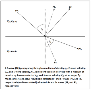
In geophysics and reflection seismology, the Zoeppritz equations are a set of equations that describe the partitioning of seismic wave energy at an interface, typically a boundary between two different layers of rock. They are named after their author, the German geophysicist Karl Bernhard Zoeppritz, who died before they were published in 1919.

Differentiation of trigonometric functions Mathematical process of finding the derivative of a trigonometric function

The differentiation of trigonometric functions is the mathematical process of finding the derivative of a trigonometric function, or its rate of change with respect to a variable. For example, the derivative of the sine function is written sin′(a) = cos(a), meaning that the rate of change of sin(x) at a particular angle x = a is given by the cosine of that angle.

Kepler orbit

In celestial mechanics, a Kepler orbit is the motion of one body relative to another, as an ellipse, parabola, or hyperbola, which forms a two-dimensional orbital plane in three-dimensional space. A Kepler orbit can also form a straight line. It considers only the point-like gravitational attraction of two bodies, neglecting perturbations due to gravitational interactions with other objects, atmospheric drag, solar radiation pressure, a non-spherical central body, and so on. It is thus said to be a solution of a special case of the two-body problem, known as the Kepler problem. As a theory in classical mechanics, it also does not take into account the effects of general relativity. Keplerian orbits can be parametrized into six orbital elements in various ways.

Law of cosines Property of all triangles on a Euclidean plane

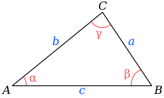
In trigonometry, the law of cosines relates the lengths of the sides of a triangle to the cosine of one of its angles. Using notation as in Fig. 1, the law of cosines states

For a plane curve C and a given fixed point O, the pedal equation of the curve is a relation between r and p where r is the distance from O to a point on C and p is the perpendicular distance from O to the tangent line to C at the point. The point O is called the pedal point and the values r and p are sometimes called the pedal coordinates of a point relative to the curve and the pedal point. It is also useful to measure the distance of O to the normal even though it is not an independent quantity and it relates to as .

Isentropic expansion waves

Isentropic expansion waves are created when a supersonic flow is redirected along a curved surface. These waves are studied to obtain a relation between deflection angle and Mach number. Each wave in this case is a Mach wave, so it is at an angle , where M is the Mach number immediately before the wave. Expansion waves are divergent because as the flow expands the value of Mach number increases, thereby decreasing the Mach angle.

References