Single-ended signaling is the simplest and most commonly used method of transmitting electrical signals over wires. One wire carries a varying voltage that represents the signal, while the other wire is connected to a reference voltage, usually ground. The main alternative to single-ended signaling is called differential signaling where the two conductors carry signals equal in magnitude but of opposite polarity.
Single-ended signaling is less expensive to implement than differential, but it has a distinct disadvantage: a single-ended system requires a power supply voltage equal to the maximum amplitude of the signal to be received whereas a differential system only requires a voltage half of the signal amplitude to be received. For a given power supply voltage then, a differential system produces signals of twice the amplitude and therefore has twice as good noise immunity (6 dB higher signal-to-noise ratio) as a single-ended system.
The main advantage of single-ended over differential signaling is that fewer wires are needed to transmit multiple signals. If there are n signals, then there are n+1 wires, one for each signal and one for ground, while differential signaling uses at least 2n wires. A disadvantage of single-ended systems that utilize a common return is that the return currents for all the signals use the same conductor (even if separate ground wires are used, the grounds are inevitably connected together at each end), and this can sometimes cause interference (crosstalk) between the signals.
Standards
Single-ended signaling is widely used, and can be seen in numerous common transmission standards, including:
SCSI interfaces for hard drives and other peripherals
Parallel ATA interfaces for hard drives and other peripherals
Connectors
A wide range of connectors can be used for single-ended signaling. Some common connectors for domestic and entertainment equipment include; Some kinds of connectors, though more often used for balanced pairs, are sometimes used for single-ended operation:
The widely used RS-232 system is an example of single-ended signaling, which uses ±12 V to represent a signal, and anything less than ±3 V to represent the lack of a signal. The high voltage levels give the signals some immunity from noise, since few naturally occurring signals can create a voltage of such magnitude. They also have the advantage of requiring only one wire per signal. However, they also have a serious disadvantage: they cannot run at high speeds. The effects of capacitance and inductance, which filter out high-frequency signals, limit the speed.
Historically, electrical telegraph used single-ended signaling with earth return, thus completely eliminating the need to provide a return conductor and substantially reducing the cost of long distance lines. Telegraph is the earliest use of the single-ended transmission line type, but is now obsolete.
In telecommunications, RS-232 or Recommended Standard 232 is a standard originally introduced in 1960 for serial communication transmission of data. It formally defines signals connecting between a DTE such as a computer terminal, and a DCE, such as a modem. The standard defines the electrical characteristics and timing of signals, the meaning of signals, and the physical size and pinout of connectors. The current version of the standard is TIA-232-F Interface Between Data Terminal Equipment and Data Circuit-Terminating Equipment Employing Serial Binary Data Interchange, issued in 1997. The RS-232 standard had been commonly used in computer serial ports and is still widely used in industrial communication devices.
In telecommunications and professional audio, a balanced line or balanced signal pair is a circuit consisting of two conductors of the same type, each of which have equal impedances along their lengths and equal impedances to ground and to other circuits. The chief advantage of the balanced line format is good rejection of common-mode noise and interference when fed to a differential device such as a transformer or differential amplifier. Common forms of balanced line are twin-lead, used for radio frequency signals and twisted pair, used for lower frequencies. They are to be contrasted to unbalanced lines, such as coaxial cable, which is designed to have its return conductor connected to ground, or circuits whose return conductor actually is ground. Balanced and unbalanced circuits can be interfaced using a device called a balun.
Low-voltage differential signaling, or LVDS, also known as TIA/EIA-644, is a technical standard that specifies electrical characteristics of a differential, serial signaling standard, but it is not a protocol. LVDS operates at low power and can run at very high speeds using inexpensive twisted-pair copper cables. LVDS is a physical layer specification only; many data communication standards and applications use it and add a data link layer as defined in the OSI model on top of it.
In telecommunication and data transmission, serial communication is the process of sending data one bit at a time, sequentially, over a communication channel or computer bus. This is in contrast to parallel communication, where several bits are sent as a whole, on a link with several parallel channels.
Balanced audio is a method of interconnecting audio equipment using balanced interfaces. This type of connection is very important in sound recording and production because it allows the use of long cables while reducing susceptibility to external noise caused by electromagnetic interference. The balanced interface guarantees that induced noise appears as common-mode voltages at the receiver which can be rejected by a differential device.
A balun is an electrical device that allows balanced and unbalanced lines to be interfaced without disturbing the impedance arrangement of either line. A balun can take many forms and may include devices that also transform impedances but need not do so. Sometimes, in the case of transformer baluns, they use magnetic coupling but need not do so. Common-mode chokes are also used as baluns and work by eliminating, rather than rejecting, common mode signals.
RS-422, also known as TIA/EIA-422, is a technical standard originated by the Electronic Industries Alliance that specifies electrical characteristics of a digital signaling circuit. It was intended to replace the older RS-232C standard with a standard that offered much higher speed, better immunity from noise, and longer cable lengths. RS-422 systems can transmit data at rates as high as 10 Mbit/s, or may be sent on cables as long as 1,200 meters (3,900 ft) at lower rates. It is closely related to RS-423, which uses the same signaling systems but on a different wiring arrangement.
An Earth-leakage circuit breaker (ELCB) is a safety device used in electrical installations with high Earth impedance to prevent shock. It detects small stray voltages on the metal enclosures of electrical equipment, and interrupts the circuit if a dangerous voltage is detected. Once widely used, more recent installations instead use residual-current devices which instead detect leakage current directly.
Differential TTL is a type of binary electrical signaling based on the TTL concept. Standards implementing differential TTL include RS-422. It enables electronic systems to be relatively immune to noise.
In an electrical system, a ground loop or earth loop occurs when two points of a circuit are intended to have the same ground reference potential but instead have a different potential between them. This is typically caused when enough current is flowing in the connection between the two ground points to produce a voltage drop and cause two points to be at different potentials. Current may be produced in a circular ground connection by electromagnetic induction.
RS-485, also known as TIA-485(-A) or EIA-485, is a standard defining the electrical characteristics of drivers and receivers for use in serial communications systems. Electrical signaling is balanced, and multipoint systems are supported. The standard is jointly published by the Telecommunications Industry Association and Electronic Industries Alliance (TIA/EIA). Digital communications networks implementing the standard can be used effectively over long distances and in electrically noisy environments. Multiple receivers may be connected to such a network in a linear, multidrop bus. These characteristics make RS-485 useful in industrial control systems and similar applications.
Differential signalling is a method for electrically transmitting information using two complementary signals. The technique sends the same electrical signal as a differential pair of signals, each in its own conductor. The pair of conductors can be wires in a twisted-pair or ribbon cable or traces on a printed circuit board.
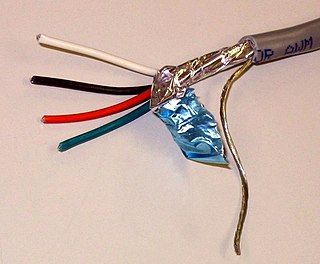
A shielded cable or screened cable is an electrical cable of one or more insulated conductors enclosed by a common conductive layer. The shield may be composed of braided strands of copper, a non-braided spiral winding of copper tape, or a layer of conducting polymer. Usually this shield is covered with a jacket.
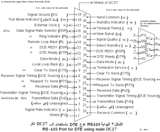
The RS-449 specification, also known as EIA-449 or TIA-449, defines the functional and mechanical characteristics of the interface between data terminal equipment, typically a computer, and data communications equipment, typically a modem or terminal server. The full title of the standard is EIA-449 General Purpose 37-Position and 9-Position Interface for Data Terminal Equipment and Data Circuit-Terminating Equipment Employing Serial Binary Data Interchange.
In a radio antenna, the feed line (feedline), or feeder, is the cable or other transmission line that connects the antenna with the radio transmitter or receiver. In a transmitting antenna, it feeds the radio frequency (RF) current from the transmitter to the antenna, where it is radiated as radio waves. In a receiving antenna it transfers the tiny RF voltage induced in the antenna by the radio wave to the receiver. In order to carry RF current efficiently, feed lines are made of specialized types of cable called transmission line. The most widely used types of feed line are coaxial cable, twin-lead, ladder line, and at microwave frequencies, waveguide.
In telecommunications and electrical engineering in general, an unbalanced line is a pair of conductors intended to carry electrical signals, which have unequal impedances along their lengths and to ground and other circuits. Examples of unbalanced lines are coaxial cable or the historic earth return system invented for the telegraph, but rarely used today. Unbalanced lines are to be contrasted with balanced lines, such as twin-lead or twisted pair which use two identical conductors to maintain impedance balance throughout the line. Balanced and unbalanced lines can be interfaced using a device called a balun.
A balanced circuit is circuitry for use with a balanced line or the balanced line itself. Balanced lines are a common method of transmitting many types of electrical communication signals between two points on two wires. In a balanced line the two signal lines are of a matched impedance to help ensure that interference induced in the line is common-mode and can be removed at the receiving end by circuitry with good common-mode rejection. To maintain the balance, circuit blocks which interface to the line, or are connected in the line, must also be balanced.
RS-423, also known as TIA/EIA-423, is a technical standard originated by the Electronic Industries Alliance that specifies electrical characteristics of a digital signaling circuit. Although it was originally intended as a successor to RS-232C offering greater cable lengths, it is not widely used. RS-423 systems can transmit data on cables as long as 1,200 meters (3,900 ft). It is closely related to RS-422, which used the same signaling systems but on a different wiring arrangement. RS-423 differed primarily in that it had a single return pin instead of one for each data pin.
Common-mode signal is the voltage common to both input terminals of an electrical device. In telecommunication, the common-mode signal on a transmission line is also known as longitudinal voltage.
Synchronous Serial Interface (SSI) is a widely used serial interface standard for industrial applications between a master and a slave. SSI is based on RS-422 standards and has a high protocol efficiency in addition to its implementation over various hardware platforms, making it very popular among sensor manufacturers. SSI was originally developed by Max Stegmann GmbH in 1984 for transmitting the position data of absolute encoders – for this reason, some servo/drive equipment manufacturers refer to their SSI port as a "Stegmann Interface". It was formerly covered by the German patent DE 34 45 617 which expired in 1990. It is very suitable for applications demanding reliability and robustness in measurements under varying industrial environments.
This page is based on this Wikipedia article Text is available under the CC BY-SA 4.0 license; additional terms may apply. Images, videos and audio are available under their respective licenses.