Electrochemistry is the branch of physical chemistry concerned with the relationship between electrical potential difference, as a measurable and quantitative phenomenon, and identifiable chemical change, with the potential difference as an outcome of a particular chemical change, or vice versa. These reactions involve electrons moving via an electronically-conducting phase between electrodes separated by an ionically conducting and electronically insulating electrolyte.
An electrode is an electrical conductor used to make contact with a nonmetallic part of a circuit. Electrodes are essential parts of batteries that can consist of a variety of materials depending on the type of battery.
Signal-to-noise ratio is a measure used in science and engineering that compares the level of a desired signal to the level of background noise. SNR is defined as the ratio of signal power to the noise power, often expressed in decibels. A ratio higher than 1:1 indicates more signal than noise.

The electrical resistance of an object is a measure of its opposition to the flow of electric current. Its reciprocal quantity is electrical conductance, measuring the ease with which an electric current passes. Electrical resistance shares some conceptual parallels with mechanical friction. The SI unit of electrical resistance is the ohm, while electrical conductance is measured in siemens (S).
Electrical resistivity is a fundamental property of a material that measures how strongly it resists electric current. A low resistivity indicates a material that readily allows electric current. Resistivity is commonly represented by the Greek letter ρ (rho). The SI unit of electrical resistivity is the ohm-meter (Ω⋅m). For example, if a 1 m3 solid cube of material has sheet contacts on two opposite faces, and the resistance between these contacts is 1 Ω, then the resistivity of the material is 1 Ω⋅m.
Space charge is an interpretation of a collection of electric charges in which excess electric charge is treated as a continuum of charge distributed over a region of space rather than distinct point-like charges. This model typically applies when charge carriers have been emitted from some region of a solid—the cloud of emitted carriers can form a space charge region if they are sufficiently spread out, or the charged atoms or molecules left behind in the solid can form a space charge region.
The van der Pauw Method is a technique commonly used to measure the resistivity and the Hall coefficient of a sample. Its power lies in its ability to accurately measure the properties of a sample of any arbitrary shape, as long as the sample is approximately two-dimensional, solid, and the electrodes are placed on its perimeter. The van der Pauw method employs a four-point probe placed around the perimeter of the sample, in contrast to the linear four point probe: this allows the van der Pauw method to provide an average resistivity of the sample, whereas a linear array provides the resistivity in the sensing direction. This difference becomes important for anisotropic materials, which can be properly measured using the Montgomery Method, an extension of the van der Pauw Method.
A network, in the context of electrical engineering and electronics, is a collection of interconnected components. Network analysis is the process of finding the voltages across, and the currents through, all network components. There are many techniques for calculating these values. However, for the most part, the techniques assume linear components. Except where stated, the methods described in this article are applicable only to linear network analysis.

Electrical impedance tomography (EIT) is a noninvasive type of medical imaging in which the electrical conductivity, permittivity, and impedance of a part of the body is inferred from surface electrode measurements and used to form a tomographic image of that part. Electrical conductivity varies considerably among various biological tissues or the movement of fluids and gases within tissues. The majority of EIT systems apply small alternating currents at a single frequency, however, some EIT systems use multiple frequencies to better differentiate between normal and suspected abnormal tissue within the same organ.

The breakdown voltage of an insulator is the minimum voltage that causes a portion of an insulator to experience electrical breakdown and become electrically conductive.
In an electric circuit, instantaneous power is the time rate of flow of energy past a given point of the circuit. In alternating current circuits, energy storage elements such as inductors and capacitors may result in periodic reversals of the direction of energy flow. Its SI unit is the watt.

Electrical resistivity tomography (ERT) or electrical resistivity imaging (ERI) is a geophysical technique for imaging sub-surface structures from electrical resistivity measurements made at the surface, or by electrodes in one or more boreholes. If the electrodes are suspended in the boreholes, deeper sections can be investigated. It is closely related to the medical imaging technique electrical impedance tomography (EIT), and mathematically is the same inverse problem. In contrast to medical EIT, however, ERT is essentially a direct current method. A related geophysical method, induced polarization, measures the transient response and aims to determine the subsurface chargeability properties.
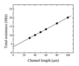
The term contact resistance refers to the contribution to the total resistance of a system which can be attributed to the contacting interfaces of electrical leads and connections as opposed to the intrinsic resistance. This effect is described by the term electrical contact resistance (ECR) and arises as the result of the limited areas of true contact at an interface and the presence of resistive surface films or oxide layers. ECR may vary with time, most often decreasing, in a process known as resistance creep. The idea of potential drop on the injection electrode was introduced by William Shockley to explain the difference between the experimental results and the model of gradual channel approximation. In addition to the term ECR, interface resistance, transitional resistance, or just simply correction term are also used. The term parasitic resistance is used as a more general term, of which it is usually assumed that contact resistance is a major component.

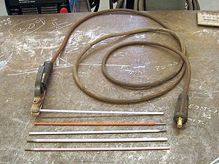
An electrode array is a configuration of electrodes used for measuring either an electric current or voltage. Some electrode arrays can operate in a bidirectional fashion, in that they can also be used to provide a stimulating pattern of electric current or voltage.
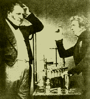
A potentiometer is an instrument for measuring voltage or 'potential difference' by comparison of an unknown voltage with a known reference voltage. If a sensitive indicating instrument is used, very little current is drawn from the source of the unknown voltage. Since the reference voltage can be produced from an accurately calibrated voltage divider, a potentiometer can provide high precision in measurement. The method was described by Johann Christian Poggendorff around 1841 and became a standard laboratory measuring technique.
Electrical cardiometry is a method based on the model of Electrical Velocimetry, and non-invasively measures stroke volume (SV), cardiac output (CO), and other hemodynamic parameters through the use of 4 surface ECG electrodes. Electrical cardiometry is a method trademarked by Cardiotronic, Inc., and is U.S. FDA approved for use on adults, children, and neonates.

Conductivity of an electrolyte solution is a measure of its ability to conduct electricity. The SI unit of conductivity is Siemens per meter (S/m).
Concrete electrical resistivity can be obtained by applying a current into the concrete and measuring the response voltage. There are different methods for measuring concrete resistivity.
Soil resistivity is a measure of how much the soil resists or conducts electric current. It is a critical factor in design of systems that rely on passing current through the Earth's surface. It is a very important parameter for finding the best location of a transmitter working on low frequiencies as such radio stations usually use ground as counterpole. An understanding of the soil resistivity and how it varies with depth in the soil is necessary to design the grounding system in an electrical substation, or for lightning conductors. It is needed for design of grounding (earthing) electrodes for substations and High-voltage direct current transmission systems. It was formerly important in earth-return telegraphy. It can also be a useful measure in agriculture as a proxy measurement for moisture content.
Electrical capacitance volume tomography (ECVT) is a non-invasive 3D imaging technology applied primarily to multiphase flows. It was first introduced by W. Warsito, Q. Marashdeh, and L.-S. Fan as an extension of the conventional electrical capacitance tomography (ECT). In conventional ECT, sensor plates are distributed around a surface of interest. Measured capacitance between plate combinations is used to reconstruct 2D images (tomograms) of material distribution. In ECT, the fringing field from the edges of the plates is viewed as a source of distortion to the final reconstructed image and is thus mitigated by guard electrodes. ECVT exploits this fringing field and expands it through 3D sensor designs that deliberately establish an electric field variation in all three dimensions. The image reconstruction algorithms are similar in nature to ECT; nevertheless, the reconstruction problem in ECVT is more complicated. The sensitivity matrix of an ECVT sensor is more ill-conditioned and the overall reconstruction problem is more ill-posed compared to ECT. The ECVT approach to sensor design allows direct 3D imaging of the outrounded geometry. This is different than 3D-ECT that relies on stacking images from individual ECT sensors. 3D-ECT can also be accomplished by stacking frames from a sequence of time intervals of ECT measurements. Because the ECT sensor plates are required to have lengths on the order of the domain cross-section, 3D-ECT does not provide the required resolution in the axial dimension. ECVT solves this problem by going directly to the image reconstruction and avoiding the stacking approach. This is accomplished by using a sensor that is inherently three-dimensional.


