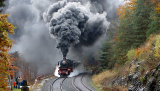
A tank locomotive or tank engine is a steam locomotive that carries its water in one or more on-board water tanks, instead of a more traditional tender. A tank engine may also have a bunker to hold fuel. There are several different types of tank locomotive, distinguished by the position and style of the water tanks and fuel bunkers. The most common type has tanks mounted either side of the boiler. This type originated about 1840 and quickly became popular for industrial tasks, and later for shunting and shorter distance main line duties. Tank locomotives have advantages and disadvantages compared to traditional tender locomotives.
The UIC classification of locomotive axle arrangements, sometimes known as German classification or German system, describes the wheel arrangement of locomotives, multiple units and trams. It is set out in the International Union of Railways (UIC) "Leaflet 650 – Standard designation of axle arrangement on locomotives and multiple-unit sets". It is used in much of the world. The United Kingdom uses the Whyte notation. The United States uses the simplified AAR wheel arrangement for modern locomotives.

This is a glossary of the components found on typical steam locomotives.

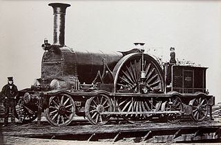
Under the Whyte notation for the classification of steam locomotives, 4-2-0 represents the wheel arrangement of four leading wheels on two axles, two powered driving wheels on one axle and no trailing wheels. This type of locomotive is often called a Jervis type, the name of the original designer.

Under the Whyte notation for the classification of steam locomotives, 4-2-2 represents the wheel arrangement of four leading wheels on two axles, two powered driving wheels on one axle, and two trailing wheels on one axle.

On a steam locomotive, a trailing wheel or trailing axle is generally an unpowered wheel or axle (wheelset) located behind the driving wheels. The axle of the trailing wheels is usually located in a trailing truck. On some large locomotives, a booster engine was mounted on the trailing truck to provide extra tractive effort when starting a heavy train and at low speeds on gradients.
Under the Whyte notation for the classification of steam locomotives, 4-2-4 represents the wheel arrangement of four leading wheels on two axles, two powered driving wheels on one axle, and four trailing wheels on two axles. This type of locomotive is often called a Huntington type.
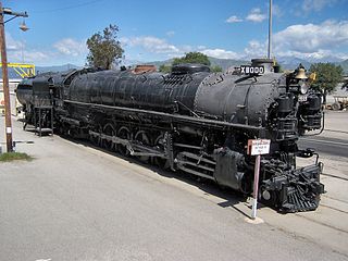
Under the Whyte notation for the classification of steam locomotives, 4-12-2 represents the wheel arrangement of four leading wheels, twelve coupled driving wheels, and two trailing wheels. This arrangement was named the Union Pacific type, after the only railroad to use it.

An 0-2-2, in the Whyte notation for the classification of steam locomotives by wheel arrangement, is one that has two coupled driving wheels followed by two trailing wheels, with no leading wheels. The configuration was briefly built by Robert Stephenson and Company for the Liverpool and Manchester Railway
A 4-14-4, in the Whyte notation is the classification of steam locomotives by wheel arrangement, is a locomotive with four leading wheels, fourteen coupled driving wheels in a rigid frame, and four trailing wheels.
B-B and Bo-Bo are the Association of American Railroads (AAR) and British classifications of wheel arrangement for railway locomotives with four axles in two individual bogies. They are equivalent to the B′B′ and Bo′Bo′ classifications in the UIC system. The arrangement of two, two-axled, bogies is a common wheel arrangement for modern electric and diesel locomotives.

A jackshaft is an intermediate shaft used to transfer power from a powered shaft such as the output shaft of an engine or motor to driven shafts such as the drive axles of a locomotive. As applied railroad locomotives in the 19th and 20th centuries, jackshafts were typically in line with the drive axles of locomotives and connected to them by side rods. In general, each drive axle on a locomotive is free to move about one inch (2.5 cm) vertically relative to the frame, with the locomotive weight carried on springs. This means that if the engine, motor or transmission is rigidly attached to the locomotive frame, it cannot be rigidly connected to the axle. This problem can be solved by mounting the jackshaft on unsprung bearings and using side-rods or chain drives.

The Dean Single, 3031 Class, or Achilles Class was a type of steam locomotive built by the British Great Western Railway between 1891 and 1899. They were designed by William Dean for passenger work. The first 30 members of the class were built as 2-2-2s of the 3001 Class.

The South African Railways Class 21 2-10-4 of 1937 was a steam locomotive.

Under the Whyte notation for the classification of steam locomotives, 2-2-2-2 could represent either the wheel arrangement of two leading wheels on one axle, four powered but uncoupled driving wheels on two axles, and two trailing wheels on one axle, or of two sets of leading wheels, two driving wheels on one axle, and two trailing wheels.

The Z21 class was a class of steam locomotives built for the New South Wales Government Railways in Australia.

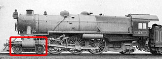
A Cartazzi axle is a design of leading or trailing wheel support used worldwide. The design was used extensively on the former LNER's Pacific steam locomotives and named after its inventor F.I. Cartazzi, formerly of the Great Northern Railway. It should not be confused with a pony truck as it does not pivot at all. The axle does, however, have sideways play built in to accommodate tight curves. Cartazzi's design causes the weight of the locomotive to exert a self-centring action on the trailing wheels.
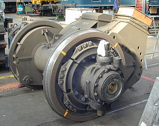
A cannon bearing or cannon box bearing is an arrangement of bearings on a shaft, usually an axle, where two bearings are mounted in an enclosed tube.