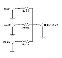
A simple three-channel passive additive mixer. More channels can be added by simply adding more input jacks and mix resistors.A "virtual ground" active additive mixer. The buffer amplifiers serve to reduce crosstalk and distortion.
An electronic mixer is a device that combines two or more electrical or electronicsignals into one or two composite output signals. There are two basic circuits that both use the term mixer, but they are very different types of circuits: additive mixers and multiplicative mixers. Additive mixers are also known as analog adders to distinguish from the related digital adder circuits.
Multiplicative mixers multiply together two time-varying input signals instantaneously (instant-by-instant). If the two input signals are both sinusoids of specified frequencies f1 and f2, then the output of the mixer will contain two new sinusoids that have the sum f1 + f2 frequency and the difference frequency absolute value |f1 - f2|.
Any nonlinear electronic block driven by two signals with frequencies f1 and f2 would generate intermodulation (mixing) products. A multiplier (which is a nonlinear device) will generate ideally only the sum and difference frequencies, whereas an arbitrary nonlinear block will also generate signals at 2·f1-3·f2, etc. Therefore, normal nonlinear amplifiers or just single diodes have been used as mixers, instead of a more complex multiplier. A multiplier usually has the advantage of rejecting – at least partly – undesired higher-order intermodulations and larger conversion gain.
Additive mixers add two or more signals, giving out a composite signal that contains the frequency components of each of the source signals. The simplest additive mixers are resistor networks, and thus purely passive, while more complex matrix mixers employ active components such as buffer amplifiers for impedance matching and better isolation.
An ideal multiplicative mixer produces an output signal equal to the product of the two input signals. In communications, a multiplicative mixer is often used together with an oscillator to modulate signal frequencies. A multiplicative mixer can be coupled with a filter to either up-convert or down-convert an input signal frequency, but they are more commonly used to down-convert to a lower frequency to allow for simpler filter designs, as done in superheterodyne receivers. In many typical circuits, the single output signal actually contains multiple waveforms, namely those at the sum and difference of the two input frequencies and harmonic waveforms. The output signal may be obtained by removing the other signal components with a filter.í
and that of the local oscillator can be represented as
For simplicity, assume that the output I of the detector is proportional to the square of the amplitude:
The output has high frequency (, and ) and constant components. In heterodyne detection, the high frequency components and usually the constant components are filtered out, leaving the intermediate (beat) frequency at . The amplitude of this last component is proportional to the amplitude of the signal radiation. With appropriate signal analysis the phase of the signal can be recovered as well.
If is equal to then the beat component is a recovered version of the original signal, with the amplitude equal to the product of and ; that is, the received signal is amplified by mixing with the local oscillator[clarification needed]. This is the basis for a Direct conversion receiver.
Implementations
Multiplicative mixers have been implemented in many ways. The most popular are Gilbert cell mixers, diode mixers, diode ring mixers (ring modulation) and switching mixers. Diode mixers take advantage of the non-linearity of diode devices to produce the desired multiplication in the squared term. They are very inefficient as most of the power output is in other unwanted terms which need filtering out. Inexpensive AM radios still use diode mixers.
Gilbert cell mixers are an arrangement of transistors that multiplies the two signals.
Switching mixers use arrays of field-effect transistors or vacuum tubes. These are used as electronic switches, to alternate the signal direction. They are controlled by the signal being mixed. They are especially popular with digitally controlled radios. Switching mixers pass more power and usually insert less distortion than Gilbert cell mixers.
In classical mechanics, a harmonic oscillator is a system that, when displaced from its equilibrium position, experiences a restoring force F proportional to the displacement x:
In mechanics and physics, simple harmonic motion is a special type of periodic motion an object experiences due to a restoring force whose magnitude is directly proportional to the distance of the object from an equilibrium position and acts towards the equilibrium position. It results in an oscillation that is described by a sinusoid which continues indefinitely.
In signal processing, group delay and phase delay are two related ways of describing how a signal's frequency components are delayed in time when passing through a linear time-invariant (LTI) system. Phase delay describes the time shift of a sinusoidal component. Group delay describes the time shift of the envelope of a wave packet, a "pack" or "group" of oscillations centered around one frequency that travel together, formed for instance by multiplying a sine wave by an envelope.
A heterodyne is a signal frequency that is created by combining or mixing two other frequencies using a signal processing technique called heterodyning, which was invented by Canadian inventor-engineer Reginald Fessenden. Heterodyning is used to shift signals from one frequency range into another, and is also involved in the processes of modulation and demodulation. The two input frequencies are combined in a nonlinear signal-processing device such as a vacuum tube, transistor, or diode, usually called a mixer.
A phase-locked loop or phase lock loop (PLL) is a control system that generates an output signal whose phase is fixed relative to the phase of an input signal. Keeping the input and output phase in lockstep also implies keeping the input and output frequencies the same, thus a phase-locked loop can also track an input frequency. And by incorporating a frequency divider, a PLL can generate a stable frequency that is a multiple of the input frequency.
In electrical engineering, impedance is the opposition to alternating current presented by the combined effect of resistance and reactance in a circuit.
In physics, angular velocity, also known as angular frequency vector, is a pseudovector representation of how the angular position or orientation of an object changes with time, i.e. how quickly an object rotates around an axis of rotation and how fast the axis itself changes direction.
In optics and in wave propagation in general, dispersion is the phenomenon in which the phase velocity of a wave depends on its frequency; sometimes the term chromatic dispersion is used for specificity to optics in particular. A medium having this common property may be termed a dispersive medium.
A resistor–capacitor circuit, or RC filter or RC network, is an electric circuit composed of resistors and capacitors. It may be driven by a voltage or current source and these will produce different responses. A first order RC circuit is composed of one resistor and one capacitor and is the simplest type of RC circuit.
An envelope detector is an electronic circuit that takes a (relatively) high-frequency amplitude modulated signal as input and provides an output, which is the demodulated envelope of the original signal.
In electronics, a mixer, or frequency mixer, is an electrical circuit that creates new frequencies from two signals applied to it. In its most common application, two signals are applied to a mixer, and it produces new signals at the sum and difference of the original frequencies. Other frequency components may also be produced in a practical frequency mixer.
In mathematics and signal processing, the Hilbert transform is a specific singular integral that takes a function, u(t) of a real variable and produces another function of a real variable H(u)(t). The Hilbert transform is given by the Cauchy principal value of the convolution with the function (see § Definition). The Hilbert transform has a particularly simple representation in the frequency domain: It imparts a phase shift of ±90° (π/2 radians) to every frequency component of a function, the sign of the shift depending on the sign of the frequency (see § Relationship with the Fourier transform). The Hilbert transform is important in signal processing, where it is a component of the analytic representation of a real-valued signal u(t). The Hilbert transform was first introduced by David Hilbert in this setting, to solve a special case of the Riemann–Hilbert problem for analytic functions.
An LC circuit, also called a resonant circuit, tank circuit, or tuned circuit, is an electric circuit consisting of an inductor, represented by the letter L, and a capacitor, represented by the letter C, connected together. The circuit can act as an electrical resonator, an electrical analogue of a tuning fork, storing energy oscillating at the circuit's resonant frequency.
In physics and engineering, a phasor is a complex number representing a sinusoidal function whose amplitude, and initial phase are time-invariant and whose angular frequency is fixed. It is related to a more general concept called analytic representation, which decomposes a sinusoid into the product of a complex constant and a factor depending on time and frequency. The complex constant, which depends on amplitude and phase, is known as a phasor, or complex amplitude, and sinor or even complexor.
A resistor–inductor circuit, or RL filter or RL network, is an electric circuit composed of resistors and inductors driven by a voltage or current source. A first-order RL circuit is composed of one resistor and one inductor, either in series driven by a voltage source or in parallel driven by a current source. It is one of the simplest analogue infinite impulse response electronic filters.
Instantaneous phase and frequency are important concepts in signal processing that occur in the context of the representation and analysis of time-varying functions. The instantaneous phase (also known as local phase or simply phase) of a complex-valued function s(t), is the real-valued function:
Ripple in electronics is the residual periodic variation of the DC voltage within a power supply which has been derived from an alternating current (AC) source. This ripple is due to incomplete suppression of the alternating waveform after rectification. Ripple voltage originates as the output of a rectifier or from generation and commutation of DC power.
Optical heterodyne detection is a method of extracting information encoded as modulation of the phase, frequency or both of electromagnetic radiation in the wavelength band of visible or infrared light. The light signal is compared with standard or reference light from a "local oscillator" (LO) that would have a fixed offset in frequency and phase from the signal if the latter carried null information. "Heterodyne" signifies more than one frequency, in contrast to the single frequency employed in homodyne detection.
The Pound–Drever–Hall (PDH) technique is a widely used and powerful approach for stabilizing the frequency of light emitted by a laser by means of locking to a stable cavity. The PDH technique has a broad range of applications including interferometric gravitational wave detectors, atomic physics, and time measurement standards, many of which also use related techniques such as frequency modulation spectroscopy. Named after R. V. Pound, Ronald Drever, and John L. Hall, the PDH technique was described in 1983 by Drever, Hall and others working at the University of Glasgow and the U. S. National Bureau of Standards. This optical technique has many similarities to an older frequency-modulation technique developed by Pound for microwave cavities.
Kapitza's pendulum or Kapitza pendulum is a rigid pendulum in which the pivot point vibrates in a vertical direction, up and down. It is named after Russian Nobel laureate physicist Pyotr Kapitza, who in 1951 developed a theory which successfully explains some of its unusual properties. The unique feature of the Kapitza pendulum is that the vibrating suspension can cause it to balance stably in an inverted position, with the bob above the suspension point. In the usual pendulum with a fixed suspension, the only stable equilibrium position is with the bob hanging below the suspension point; the inverted position is a point of unstable equilibrium, and the smallest perturbation moves the pendulum out of equilibrium. In nonlinear control theory the Kapitza pendulum is used as an example of a parametric oscillator that demonstrates the concept of "dynamic stabilization".
This page is based on this Wikipedia article Text is available under the CC BY-SA 4.0 license; additional terms may apply. Images, videos and audio are available under their respective licenses.