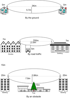
A Fresnel zone, named after physicist Augustin-Jean Fresnel, is one of a series of confocal prolate ellipsoidal regions of space between and around a transmitter and a receiver. The primary wave will travel in a relative straight line from the transmitter to the receiver. Aberrant transmitted radio, sound, or light waves which are transmitted at the same time can follow slightly different paths before reaching a receiver, especially if there are obstructions or deflecting objects between the two. The two waves can arrive at the receiver at slightly different times and the aberrant wave may arrive out of phase with the primary wave due to the different path lengths. Depending on the magnitude of the phase difference between the two waves, the waves can interfere constructively or destructively. The size of the calculated Fresnel zone at any particular distance from the transmitter and receiver can help to predict whether obstructions or discontinuities along the path will cause significant interference.

In antenna theory, a phased array usually means an electronically scanned array, a computer-controlled array of antennas which creates a beam of radio waves that can be electronically steered to point in different directions without moving the antennas.

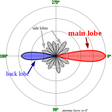
In the field of antenna design the term radiation pattern refers to the directional (angular) dependence of the strength of the radio waves from the antenna or other source.

Radio waves are a type of electromagnetic radiation with the longest wavelengths in the electromagnetic spectrum, typically with frequencies of 300 gigahertz (GHz) and below. At 300 GHz, the corresponding wavelength is 1 mm ; at 30 Hz the corresponding wavelength is 10,000 kilometers. Like all electromagnetic waves, radio waves in a vacuum travel at the speed of light, and in the Earth's atmosphere at a close, but slightly lower speed. Radio waves are generated by charged particles undergoing acceleration, such as time-varying electric currents. Naturally occurring radio waves are emitted by lightning and astronomical objects, and are part of the blackbody radiation emitted by all warm objects.

Medium wave (MW) is the part of the medium frequency (MF) radio band used mainly for AM radio broadcasting. The spectrum provides about 120 channels with more limited sound quality than FM stations on the FM broadcast band. During the daytime, reception is usually limited to more local stations, though this is dependent on the signal conditions and quality of radio receiver used. Improved signal propagation at night allows the reception of much longer distance signals. This can cause increased interference because on most channels multiple transmitters operate simultaneously worldwide. In addition, amplitude modulation (AM) is often more prone to interference by various electronic devices, especially power supplies and computers. Strong transmitters cover larger areas than on the FM broadcast band but require more energy and longer antennas. Digital modes are possible but have not reached momentum yet.

In radio engineering, an antenna or aerial is the interface between radio waves propagating through space and electric currents moving in metal conductors, used with a transmitter or receiver. In transmission, a radio transmitter supplies an electric current to the antenna's terminals, and the antenna radiates the energy from the current as electromagnetic waves. In reception, an antenna intercepts some of the power of a radio wave in order to produce an electric current at its terminals, that is applied to a receiver to be amplified. Antennas are essential components of all radio equipment.

A parabolic antenna is an antenna that uses a parabolic reflector, a curved surface with the cross-sectional shape of a parabola, to direct the radio waves. The most common form is shaped like a dish and is popularly called a dish antenna or parabolic dish. The main advantage of a parabolic antenna is that it has high directivity. It functions similarly to a searchlight or flashlight reflector to direct radio waves in a narrow beam, or receive radio waves from one particular direction only. Parabolic antennas have some of the highest gains, meaning that they can produce the narrowest beamwidths, of any antenna type. In order to achieve narrow beamwidths, the parabolic reflector must be much larger than the wavelength of the radio waves used, so parabolic antennas are used in the high frequency part of the radio spectrum, at UHF and microwave (SHF) frequencies, at which the wavelengths are small enough that conveniently-sized reflectors can be used.

Effective radiated power (ERP), synonymous with equivalent radiated power, is an IEEE standardized definition of directional radio frequency (RF) power, such as that emitted by a radio transmitter. It is the total power in watts that would have to be radiated by a half-wave dipole antenna to give the same radiation intensity as the actual source antenna at a distant receiver located in the direction of the antenna's strongest beam. ERP measures the combination of the power emitted by the transmitter and the ability of the antenna to direct that power in a given direction. It is equal to the input power to the antenna multiplied by the gain of the antenna. It is used in electronics and telecommunications, particularly in broadcasting to quantify the apparent power of a broadcasting station experienced by listeners in its reception area.

A directional antenna or beam antenna is an antenna which radiates or receives greater power in specific directions allowing increased performance and reduced interference from unwanted sources. Directional antennas provide increased performance over dipole antennas—or omnidirectional antennas in general—when greater concentration of radiation in a certain direction is desired.

Direction finding (DF), or radio direction finding (RDF), is – in accordance with International Telecommunication Union (ITU) – defined as radio location that uses the reception of radio waves to determine the direction in which a radio station or an object is located. This can refer to radio or other forms of wireless communication, including radar signals detection and monitoring (ELINT/ESM). By combining the direction information from two or more suitably spaced receivers, the source of a transmission may be located via triangulation. Radio direction finding is used in the navigation of ships and aircraft, to locate emergency transmitters for search and rescue, for tracking wildlife, and to locate illegal or interfering transmitters. RDF was important in combating German threats during both the World War II Battle of Britain and the long running Battle of the Atlantic. In the former, the Air Ministry also used RDF to locate its own fighter groups and vector them to detected German raids.
The Beverage antenna or "wave antenna" is a long-wire receiving antenna mainly used in the low frequency and medium frequency radio bands, invented by Harold H. Beverage in 1921. It is used by amateur radio, shortwave listening, and longwave radio DXers and military applications.

In antenna engineering, sidelobes are the lobes of the far field radiation pattern of an antenna or other radiation source, that are not the main lobe.
A mast radiator is a radio mast or tower in which the metal structure itself is energized and functions as an antenna. This design, first used widely in the 1930s, is commonly used for transmitting antennas operating at low frequencies, in the LF and MF bands, in particular those used for AM radio broadcasting stations. The conductive steel mast is electrically connected to the transmitter. Its base is usually mounted on a nonconductive support to insulate it from the ground. A mast radiator is a form of monopole antenna.
A broadcast transmitter is an electronic device which radiates radio waves modulated with information content intended to be received by the general public. Examples are a radio broadcasting transmitter which transmits audio (sound) to broadcast radio receivers (radios) owned by the public, or a television transmitter, which transmits moving images (video) to television receivers (televisions). The term often includes the antenna which radiates the radio waves, and the building and facilities associated with the transmitter. A broadcasting station consists of a broadcast transmitter along with the production studio which originates the broadcasts. Broadcast transmitters must be licensed by governments, and are restricted to specific frequencies and power levels. Each transmitter is assigned a unique identifier consisting of a string of letters and numbers called a callsign, which must be used in all broadcasts.
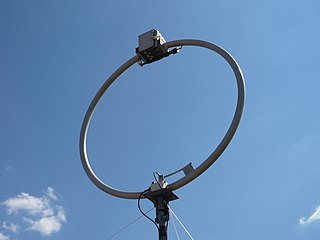
A loop antenna is a radio antenna consisting of a loop or coil of wire, tubing, or other electrical conductor, that is usually fed by a balanced source or feeding a balanced load. Within this physical description there are two distinct types:

A television antenna is an antenna specifically designed for use with a television receiver (TV) to receive over-the-air broadcast television signals from a television station. Television reception is dependent upon the antenna as well as the transmitter. Terrestrial television is broadcast on frequencies from about 47 to 250 MHz in the very high frequency (VHF) band, and 470 to 960 MHz in the ultra high frequency (UHF) band in different countries. Television antennas are manufactured in two different types: "indoor" antennas, to be located on top of or next to the television set, and "outdoor" antennas, mounted on a mast on top of the owner's house. They can also be mounted in a loft or attic, where the dry conditions and increased elevation are advantageous for reception and antenna longevity. Outdoor antennas are more expensive and difficult to install, but are necessary for adequate reception in fringe areas far from television stations. The most common types of indoor antennas are the dipole and loop antennas, and for outdoor antennas the Yagi, log periodic, and for UHF channels the multi-bay reflective array antenna.
A monopole antenna is a class of radio antenna consisting of a straight rod-shaped conductor, often mounted perpendicularly over some type of conductive surface, called a ground plane. The driving signal from the transmitter is applied, or for receiving antennas the output signal to the receiver is taken, between the lower end of the monopole and the ground plane. One side of the antenna feedline is attached to the lower end of the monopole, and the other side is attached to the ground plane, which is often the Earth. This contrasts with a dipole antenna which consists of two identical rod conductors, with the signal from the transmitter applied between the two halves of the antenna.

Radio is the technology of signaling and communicating using radio waves. Radio waves are electromagnetic waves of frequency between 30 hertz (Hz) and 300 gigahertz (GHz). They are generated by an electronic device called a transmitter connected to an antenna which radiates the waves, and received by another antenna connected to a radio receiver. Radio is very widely used in modern technology, in radio communication, radar, radio navigation, remote control, remote sensing, and other applications.

An antenna array is a set of multiple connected antennas which work together as a single antenna, to transmit or receive radio waves. The individual antennas are usually connected to a single receiver or transmitter by feedlines that feed the power to the elements in a specific phase relationship. The radio waves radiated by each individual antenna combine and superpose, adding together to enhance the power radiated in desired directions, and cancelling to reduce the power radiated in other directions. Similarly, when used for receiving, the separate radio frequency currents from the individual antennas combine in the receiver with the correct phase relationship to enhance signals received from the desired directions and cancel signals from undesired directions. More sophisticated array antennas may have multiple transmitter or receiver modules, each connected to a separate antenna element or group of elements.
In radio systems, many different antenna types are used whose properties are especially crafted for particular applications. Antennas can be classified in various ways. The list below groups together antennas under common operating principles, following the way antennas are classified in many engineering textbooks.