
A scanning electron microscope (SEM) is a type of electron microscope that produces images of a sample by scanning the surface with a focused beam of electrons. The electrons interact with atoms in the sample, producing various signals that contain information about the surface topography and composition of the sample. The electron beam is scanned in a raster scan pattern, and the position of the beam is combined with the intensity of the detected signal to produce an image. In the most common SEM mode, secondary electrons emitted by atoms excited by the electron beam are detected using a secondary electron detector. The number of secondary electrons that can be detected, and thus the signal intensity, depends, among other things, on specimen topography. Some SEMs can achieve resolutions better than 1 nanometer.

Lidar is a method for determining ranges by targeting an object with a laser and measuring the time for the reflected light to return to the receiver. Lidar can also be used to make digital 3-D representations of areas on the earth's surface and ocean bottom, due to differences in laser return times, and by varying laser wavelengths. It has terrestrial, airborne, and mobile applications.
In materials science, superplasticity is a state in which solid crystalline material is deformed well beyond its usual breaking point, usually over about 600% during tensile deformation. Such a state is usually achieved at high homologous temperature. Examples of superplastic materials are some fine-grained metals and ceramics. Other non-crystalline materials (amorphous) such as silica glass and polymers also deform similarly, but are not called superplastic, because they are not crystalline; rather, their deformation is often described as Newtonian fluid. Superplastically deformed material gets thinner in a very uniform manner, rather than forming a "neck" that leads to fracture. Also, the formation of microvoids, which is another cause of early fracture, is inhibited.
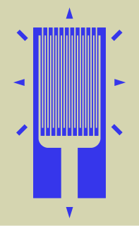
A strain gauge is a device used to measure strain on an object. Invented by Edward E. Simmons and Arthur C. Ruge in 1938, the most common type of strain gauge consists of an insulating flexible backing which supports a metallic foil pattern. The gauge is attached to the object by a suitable adhesive, such as cyanoacrylate. As the object is deformed, the foil is deformed, causing its electrical resistance to change. This resistance change, usually measured using a Wheatstone bridge, is related to the strain by the quantity known as the gauge factor.
Stress–strain analysis is an engineering discipline that uses many methods to determine the stresses and strains in materials and structures subjected to forces. In continuum mechanics, stress is a physical quantity that expresses the internal forces that neighboring particles of a continuous material exert on each other, while strain is the measure of the deformation of the material.

Photogrammetry is the science and technology of obtaining reliable information about physical objects and the environment through the process of recording, measuring and interpreting photographic images and patterns of electromagnetic radiant imagery and other phenomena.

Sheet metal is metal formed by an industrial process into thin, flat pieces. Sheet metal is one of the fundamental forms used in metalworking, and it can be cut and bent into a variety of shapes. Countless everyday objects are fabricated from sheet metal. Thicknesses can vary significantly; extremely thin sheets are considered foil or leaf, and pieces thicker than 6 mm (0.25 in) are considered plate steel or "structural steel".
Surface metrology is the measurement of small-scale features on surfaces, and is a branch of metrology. Surface primary form, surface fractality and surface roughness are the parameters most commonly associated with the field. It is important to many disciplines and is mostly known for the machining of precision parts and assemblies which contain mating surfaces or which must operate with high internal pressures.

A coordinate measuring machine (CMM) is a device that measures the geometry of physical objects by sensing discrete points on the surface of the object with a probe. Various types of probes are used in CMMs, including mechanical, optical, laser, and white light. Depending on the machine, the probe position may be manually controlled by an operator or it may be computer controlled. CMMs typically specify a probe's position in terms of its displacement from a reference position in a three-dimensional Cartesian coordinate system. In addition to moving the probe along the X, Y, and Z axes, many machines also allow the probe angle to be controlled to allow measurement of surfaces that would otherwise be unreachable.
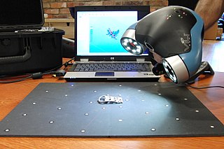
3D scanning is the process of analyzing a real-world object or environment to collect data on its shape and possibly its appearance. The collected data can then be used to construct digital 3D models.
InspecVision Ltd. is a UK engineering company based in Mallusk, Northern Ireland. The company was established in 2003. A manufacturer of computer vision inspection systems, it is one of several local hi-tech companies created as spinoffs or inspired by research conducted at the Queen's University of Belfast.
Motion analysis is used in computer vision, image processing, high-speed photography and machine vision that studies methods and applications in which two or more consecutive images from an image sequences, e.g., produced by a video camera or high-speed camera, are processed to produce information based on the apparent motion in the images. In some applications, the camera is fixed relative to the scene and objects are moving around in the scene, in some applications the scene is more or less fixed and the camera is moving, and in some cases both the camera and the scene are moving.

Deep drawing is a sheet metal forming process in which a sheet metal blank is radially drawn into a forming die by the mechanical action of a punch. It is thus a shape transformation process with material retention. The process is considered "deep" drawing when the depth of the drawn part exceeds its diameter. This is achieved by redrawing the part through a series of dies. The flange region experiences a radial drawing stress and a tangential compressive stress due to the material retention property. These compressive stresses result in flange wrinkles. Wrinkles can be prevented by using a blank holder, the function of which is to facilitate controlled material flow into the die radius.
Digital image correlation and tracking is an optical method that employs tracking and image registration techniques for accurate 2D and 3D measurements of changes in images. This method is often used to measure full-field displacement and strains, and it is widely applied in many areas of science and engineering, with new applications being found all the time. Compared to strain gages and extensometers, the amount of information gathered about the fine details of deformation during mechanical tests is increased due to the ability to provide both local and average data using digital image correlation.
A forming limit diagram, also known as a forming limit curve, is used in sheet metal forming for predicting forming behavior of sheet metal. The diagram attempts to provide a graphical description of material failure tests, such as a punched dome test.
Formability is the ability of a given metal workpiece to undergo plastic deformation without being damaged. The plastic deformation capacity of metallic materials, however, is limited to a certain extent, at which point, the material could experience tearing or fracture (breakage).

In technical applications of 3D computer graphics (CAx) such as computer-aided design and computer-aided manufacturing, surfaces are one way of representing objects. The other ways are wireframe and solids. Point clouds are also sometimes used as temporary ways to represent an object, with the goal of using the points to create one or more of the three permanent representations.
Today the metal forming industry is making increasing use of simulation to evaluate the performing of dies, processes and blanks prior to building try-out tooling. Finite element analysis (FEA) is the most common method of simulating sheet metal forming operations to determine whether a proposed design will produce parts free of defects such as fracture or wrinkling.
This is a glossary of terms relating to computer graphics.
Geological structure measurement by LiDAR technology is a remote sensing method applied in structural geology. It enables monitoring and characterisation of rock bodies. This method's typical use is to acquire high resolution structural and deformational data for identifying geological hazards risk, such as assessing rockfall risks or studying pre-earthquake deformation signs.