
Most high power transmitter amplifiers are of valve construction because of the high power required.
Most high power transmitter amplifiers are of valve construction because of the high power required.
Since valves are designed to operate with much higher resistive loads than solid state devices, the most common anode circuit is a tuned LC circuit where the anodes are connected at a voltage node. This circuit is often known as the anode tank circuit.

An example of this used at VHF/UHF could include the 4CX250B; an example of a twin tetrode would be the QQV06/40A. The tetrode has a screen grid which is between the anode and the first grid. This is grounded at the operating frequency, but carries a DC potential, normally 10 to 50% of the plate voltage. The screen grid serves to increase the stage gain while also providing shielding which increases the stability of the circuit by reducing the effective capacitance between the first grid and the anode.
For very high gain circuits, the shielding effect of the screen may not be sufficient to prevent all coupling from the plate back to the grid. Even a small amount of feedback may cause tuning difficulties and perhaps even self oscillation. Coupling of energy from the output back into the input can also occur due to poor circuit layout. It is therefore often necessary to add a neutralization circuit, which feeds some of the output signal back to the input with proper amplitude and opposite phase so as to cancel out the above-mentioned undesirable effects.
In common with all three basic designs shown here the anode of the valve is connected to an LC circuit to tune the plate circuit to resonance. Power may be coupled to the antenna via an additional inductive link as shown. More commonly modern circuits use a Pi network to resonate the plate circuit and match it to the antenna while also reducing harmonics.
For a fixed anode voltage the anode current of a triode can be described by the following equation
For a tetrode the equation will be:
Note that because the second grid is further away from the cathode, the values of the constants K, for the second grid will be smaller than those for the first grid.
As the second grid (screen grid) in a tetrode is maintained at a constant potential the equation for the tetrode can be reduced back to that of the triode as long as the screen grid is kept at the same potential.
In short the anode current is controlled by the electrical potential (voltage) of the first grid. A DC bias is applied to the valve to ensure that the part of the transfer equation which is most suitable to the required application is used.
The input signal is able to perturb (change) the potential of the grid, and this in turn will change the anode current. Another term for the anode in a valve is the plate so hence on many designs the anode current is named the plate current.
In the RF designs shown on this page between the anode and the high voltage supply (known by convention as B+) is a tuned circuit. This tuned circuit has been brought to resonance, and in a class A design can be thought of as a resistance. This is because a resistive load is coupled to the tuned circuit. In audio amplifiers the resistive load (loudspeaker) is coupled via a transformer to the amplifier. In short the load formed by the loudspeaker driven via the transformer can be thought of as a resistor wired between the valves anode and B+.
As the current flowing through the anode connection is controlled by the grid, then the current flowing through the load is also controlled by the grid.
One of the disadvantages of a tuned grid compared to other RF designs is the neutralization is required.

An example of a passive grid used at VHF/UHF frequencies include the 4CX250B; an example of a twin tetrode would be the QQV06/40A. The tetrode has a screen grid which is between the anode and the first grid, the purpose of the screen grid is to increase the stability of the circuit by reducing the capacitance between the first grid and the anode. The combination of the effects of the screen grid and the damping resistor often allow the use of this design without neutralization.
The signals come into the circuit through a capacitor, they are then applied to the valve's first grid directly. The value of the grid resistor determines the gain of the amplifier stage. The higher the resistor the greater the gain, the lower the damping effect and the greater the risk of instability. With this type of stage good layout is less vital.
Passive grid design is ideal for audio equipment, because audio equipment must be more broadband than RF equipment. A RF device might be required to operate over the range 144 to 146 MHz (1.4% of an octave) while an audio amp might be required to operate over the range 20 Hz to 20 kHz, a range of three orders of magnitude.

This design uses a triode. The grid current drawn in this system is higher than that required for the other two basic designs. Because of this, valves such as the 4CX250B are not suitable for this circuit. This circuit design has been used at 1296 MHz using disk seal triode valves such as the 2C39A.
The grid is kept at ground potential, and drive is applied to the cathode through a capacitor. The heater supply must be isolated with great care from the cathode as unlike the other designs, the cathode is not connected to RF ground. The cathode may be at the same DC potential as the grid if a valve such as the 811A (zero bias triode) is used, otherwise the cathode must be positive with respect to the grid to provide proper bias. This may be done by putting a zener diode between the cathode and ground, or by connecting a suitable power supply to the cathode.

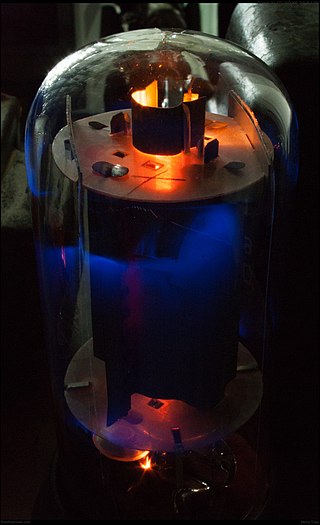
A triode is an electronic amplifying vacuum tube consisting of three electrodes inside an evacuated glass envelope: a heated filament or cathode, a grid, and a plate (anode). Developed from Lee De Forest's 1906 Audion, a partial vacuum tube that added a grid electrode to the thermionic diode, the triode was the first practical electronic amplifier and the ancestor of other types of vacuum tubes such as the tetrode and pentode. Its invention helped make amplified radio technology and long-distance telephony possible. Triodes were widely used in consumer electronics devices such as radios and televisions until the 1970s, when transistors replaced them. Today, their main remaining use is in high-power RF amplifiers in radio transmitters and industrial RF heating devices. In recent years there has been a resurgence in demand for low power triodes due to renewed interest in tube-type audio systems by audiophiles who prefer the sound of tube-based electronics.

A vacuum tube, electron tube, valve, or tube, is a device that controls electric current flow in a high vacuum between electrodes to which an electric potential difference has been applied.

A rectifier is an electrical device that converts alternating current (AC), which periodically reverses direction, to direct current (DC), which flows in only one direction. The reverse operation is performed by an inverter.
A tetrode is a vacuum tube having four active electrodes. The four electrodes in order from the centre are: a thermionic cathode, first and second grids, and a plate. There are several varieties of tetrodes, the most common being the screen-grid tube and the beam tetrode. In screen-grid tubes and beam tetrodes, the first grid is the control grid and the second grid is the screen grid. In other tetrodes one of the grids is a control grid, while the other may have a variety of functions.
A valve amplifier or tube amplifier is a type of electronic amplifier that uses vacuum tubes to increase the amplitude or power of a signal. Low to medium power valve amplifiers for frequencies below the microwaves were largely replaced by solid state amplifiers in the 1960s and 1970s. Valve amplifiers can be used for applications such as guitar amplifiers, satellite transponders such as DirecTV and GPS, high quality stereo amplifiers, military applications and very high power radio and UHF television transmitters.

A thyratron is a type of gas-filled tube used as a high-power electrical switch and controlled rectifier. Thyratrons can handle much greater currents than similar hard-vacuum tubes. Electron multiplication occurs when the gas becomes ionized, producing a phenomenon known as a Townsend discharge. Gases used include mercury vapor, xenon, neon, and hydrogen. Unlike a vacuum tube (valve), a thyratron cannot be used to amplify signals linearly.

The pentagrid converter is a type of radio receiving valve with five grids used as the frequency mixer stage of a superheterodyne radio receiver.

The control grid is an electrode used in amplifying thermionic valves such as the triode, tetrode and pentode, used to control the flow of electrons from the cathode to the anode (plate) electrode. The control grid usually consists of a cylindrical screen or helix of fine wire surrounding the cathode, and is surrounded in turn by the anode. The control grid was invented by Lee De Forest, who in 1906 added a grid to the Fleming valve to create the first amplifying vacuum tube, the Audion (triode).

In electronics, the dynatron oscillator, invented in 1918 by Albert Hull at General Electric, is an obsolete vacuum tube electronic oscillator circuit which uses a negative resistance characteristic in early tetrode vacuum tubes, caused by a process called secondary emission. It was the first negative resistance vacuum tube oscillator. The dynatron oscillator circuit was used to a limited extent as beat frequency oscillators (BFOs), and local oscillators in vacuum tube radio receivers as well as in scientific and test equipment from the 1920s to the 1940s but became obsolete around World War 2 due to the variability of secondary emission in tubes.

A beam tetrode, sometimes called a beam power tube, is a type of vacuum tube or thermionic valve that has two grids and forms the electron stream from the cathode into multiple partially collimated beams to produce a low potential space charge region between the anode and screen grid to return anode secondary emission electrons to the anode when the anode potential is less than that of the screen grid. Beam tetrodes are usually used for power amplification, from audio frequency to radio frequency. The beam tetrode produces greater output power than a triode or pentode with the same anode supply voltage. The first beam tetrode marketed was the Marconi N40, introduced in 1935. Beam tetrodes manufactured and used in the 21st century include the 4CX250B, KT66 and variants of the 6L6.

A pentode is an electronic device having five electrodes. The term most commonly applies to a three-grid amplifying vacuum tube or thermionic valve that was invented by Gilles Holst and Bernhard D.H. Tellegen in 1926. The pentode was developed from the screen-grid tube or shield-grid tube by the addition of a grid between the screen grid and the plate. The screen-grid tube was limited in performance as an amplifier due to secondary emission of electrons from the plate. The additional grid is called the suppressor grid. The suppressor grid is usually operated at or near the potential of the cathode and prevents secondary emission electrons from the plate from reaching the screen grid. The addition of the suppressor grid permits much greater output signal amplitude to be obtained from the plate of the pentode in amplifier operation than from the plate of the screen-grid tube at the same plate supply voltage. Pentodes were widely manufactured and used in electronic equipment until the 1960s to 1970s, during which time transistors replaced tubes in new designs. During the first quarter of the 21st century, a few pentode tubes have been in production for high power radio frequency applications, musical instrument amplifiers, home audio and niche markets.
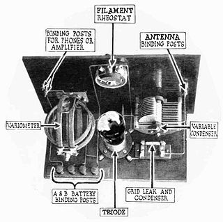
A grid leak detector is an electronic circuit that demodulates an amplitude modulated alternating current and amplifies the recovered modulating voltage. The circuit utilizes the non-linear cathode to control grid conduction characteristic and the amplification factor of a vacuum tube. Invented by Lee De Forest around 1912, it was used as the detector (demodulator) in the first vacuum tube radio receivers until the 1930s.
In Europe, the principal method of numbering vacuum tubes was the nomenclature used by the Philips company and its subsidiaries Mullard in the UK, Valvo(de, it) in Germany, Radiotechnique (Miniwatt-Dario brand) in France, and Amperex in the United States, from 1934 on. Adhering manufacturers include AEG (de), CdL (1921, French Mazda brand), CIFTE (fr, Mazda-Belvu brand), EdiSwan (British Mazda brand), Lorenz (de), MBLE(fr, nl), RCA (us), RFT(de, sv) (de), Siemens (de), Telefunken (de), Tesla (cz), Toshiba (ja), Tungsram (hu), and Unitra. This system allocated meaningful codes to tubes based on their function and became the starting point for the Pro Electron naming scheme for active devices.
Ultra-linear electronic circuits are those used to couple a tetrode or pentode vacuum-tube to a load.
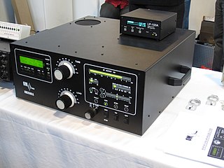
A valve RF amplifier or tube amplifier (U.S.) is a device for electrically amplifying the power of an electrical radio frequency signal.
Technical specifications and detailed information on the valve audio amplifier, including its development history.
A magic eye tube or tuning indicator, in technical literature called an electron-ray indicator tube, is a vacuum tube which gives a visual indication of the amplitude of an electronic signal, such as an audio output, radio-frequency signal strength, or other functions. The magic eye is a specific type of such a tube with a circular display similar to the EM34 illustrated. Its first broad application was as a tuning indicator in radio receivers, to give an indication of the relative strength of the received radio signal, to show when a radio station was properly tuned in.
The Cathode follower oscillator is an electronic oscillator circuit in which the oscillation frequency is determined by a tuned circuit consisting of capacitors and inductors, that is, an LC oscillator. The circuit is also known as differential amplifier oscillator, emitter follower oscillator, source-coupled oscillator or Peltz oscillator. This oscillator uses one connection to get a signal from the LC-circuit and feeds an amplified signal back. The amplifier is a long-tail pair of two triodes, two bipolar transistors or two junction FETs.

