This article needs additional citations for verification .(June 2025) |
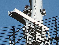 AN/SPS-55 antenna aboard USS Samuel B. Roberts (FFG-58) | |
| Country of origin | United States |
|---|---|
| Manufacturer | Cardion Electronics |
| Introduced | 1971 |
| Type | Navigation radar |
| Frequency | 9.05–10 GHz (3.31–3.00 cm) X-band |
| RPM | 16 rpm [1] |
| Range | >50 miles (43.4 nmi; 80.5 km) [1] |
| Azimuth | 1.5º |
| Elevation | +/-10° centered on the horizon |
| Power | 160 kW peak |
The AN/SPS-55 is a solid state surface search and navigation radar. It was developed by Cardion Electronics for the U.S. Navy under a contract awarded in 1971. It was originally developed for a class of ships known as Patrol Frigates, but it was also installed on numerous Cruisers, Destroyers, and Minesweepers. It is an I band radar and its antenna consists of two waveguide slotted arrays mounted back-to-back. One array provides linear polarisation and the other provides circular polarisation. Polarisation is user selectable and the circular polarised array is more effective in reducing returns from precipitation. [2]
Contents
In accordance with the Joint Electronics Type Designation System (JETDS), the "AN/SPS-55" designation represents the 55th design of an Army-Navy electronic device for surface ship search radar system. The JETDS system also now is used to name all Department of Defense electronic systems.