The aspect ratio of a geometric shape is the ratio of its sizes in different dimensions. For example, the aspect ratio of a rectangle is the ratio of its longer side to its shorter side—the ratio of width to height, when the rectangle is oriented as a "landscape".

ISO 216 is an international standard for paper sizes, used around the world except in North America and parts of Latin America. The standard defines the "A", "B" and "C" series of paper sizes, including A4, the most commonly available paper size worldwide. Two supplementary standards, ISO 217 and ISO 269, define related paper sizes; the ISO 269 "C" series is commonly listed alongside the A and B sizes.

Paper size standards govern the size of sheets of paper used as writing paper, stationery, cards, and for some printed documents.

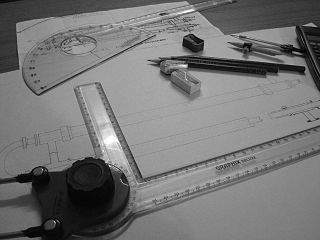
An engineering drawing is a type of technical drawing that is used to convey information about an object. A common use is to specify the geometry necessary for the construction of a component and is called a detail drawing. Usually, a number of drawings are necessary to completely specify even a simple component. These drawings are linked together by a "master drawing." This "master drawing" is more commonly known as an assembly drawing. The assembly drawing gives the drawing numbers of the subsequent detailed components, quantities required, construction materials and possibly 3D images that can be used to locate individual items. Although mostly consisting of pictographic representations, abbreviations and symbols are used for brevity and additional textual explanations may also be provided to convey the necessary information.

Geometric dimensioning and tolerancing (GD&T) is a system for defining and communicating engineering tolerances via a symbolic language on engineering drawings and computer-generated 3D models that describes a physical object's nominal geometry and the permissible variation thereof. GD&T is used to define the nominal geometry of parts and assemblies, the allowable variation in size, form, orientation, and location of individual features, and how features may vary in relation to one another such that a component is considered satisfactory for its intended use. Dimensional specifications define the nominal, as-modeled or as-intended geometry, while tolerance specifications define the allowable physical variation of individual features of a part or assembly.

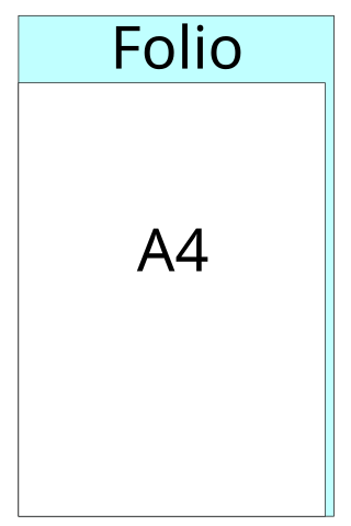
Foolscap folio is paper cut to the size of 8+1⁄2 × 13+1⁄2 in (216 × 343 mm) for printing or to 8 × 13 in (203 × 330 mm) for "normal" writing paper (foolscap). This was a traditional paper size used in some parts of Europe, and the British Commonwealth, before the adoption of the international standard A4 paper.

A hole punch, also known as hole puncher, or paper puncher, is an office tool that is used to create holes in sheets of paper, often for the purpose of collecting the sheets in a binder or folder. A hole punch can also refer to similar tools for other materials, such as leather, cloth, or plastic or metal sheets.
In industrial design, preferred numbers are standard guidelines for choosing exact product dimensions within a given set of constraints. Product developers must choose numerous lengths, distances, diameters, volumes, and other characteristic quantities. While all of these choices are constrained by considerations of functionality, usability, compatibility, safety or cost, there usually remains considerable leeway in the exact choice for many dimensions.

Letter or ANSI Letter is a paper size standard defined by the American National Standards Institute, commonly used as home or office stationery in the United States, Canada, Chile, Colombia, Costa Rica, Mexico, Panama, Guatemala, the Dominican Republic and the Philippines. It measures 8.5 by 11 inches and is similar in use to the A4 paper standard at 210 mm × 297 mm used by most other countries, defined in ISO 216 by the International Organization for Standardization.
Drill bits are the cutting tools of drilling machines. They can be made in any size to order, but standards organizations have defined sets of sizes that are produced routinely by drill bit manufacturers and stocked by distributors.
Product and manufacturing information, also abbreviated PMI, conveys non-geometric attributes in 3D computer-aided design (CAD) and Collaborative Product Development systems necessary for manufacturing product components and assemblies. PMI may include geometric dimensions and tolerances, 3D annotation (text) and dimensions, surface finish, and material specifications. PMI is used in conjunction with the 3D model within model-based definition to allow for the elimination of 2D drawings for data set utilization.
CAD Standards are a set of guidelines for the way Computer-aided drafting (CAD), or (CADD) Computer Aided Design and Drawing, drawings should appear, to improve productivity and interchange of CAD documents between different offices and CAD programs, especially in architecture and engineering.
ASME Y14.41 is a standard published by American Society of Mechanical Engineers (ASME) which establishes requirements and reference documents applicable to the preparation and revision of digital product definition data, which pertains to CAD software and those who use CAD software to create the product definition within the 3D model. ASME issued the first version of this industrial standard on Aug 15, 2003 as ASME Y14.41-2003. It was immediately adopted by several industrial organizations, as well as the Department of Defense (DOD). The latest revision of ASME Y14.41 was issued on Jan 23, 2019 as ASME Y14.41-2019.

An exercise book or composition book is a notebook that is used in schools to copy down schoolwork and notes. A student will usually have a different exercise book for each separate lesson or subject.
The ISO 217:2013 standard defines the RA and SRA paper formats.
Printing and writing papers are paper grades used for newspapers, magazines, catalogs, books, notebooks, commercial printing, business forms, stationeries, copying and digital printing. About 1/3 of the total pulp and paper marked is printing and writing papers. The pulp or fibers used in printing and writing papers are extracted from wood using a chemical or mechanical process.
Standard photographic print sizes are used in photographic printing. Cut sheets of paper meant for printing photographs are commonly sold in these sizes.

Width across flats is the distance between two parallel surfaces on the head of a screw or bolt, or a nut, mostly for torque transmission by positive locking.

Preferred metric sizes are a set of international standards and de facto standards that are designed to make using the metric system easier and simpler, especially in engineering and construction practices. One of the methods used to arrive at these preferred sizes is the use of preferred numbers and convenient numbers, such as the Renard series and 1-2-5 series, to limit the number of different sizes of components needed.
ASME Y14.5 is a standard published by the American Society of Mechanical Engineers (ASME) to establish rules, symbols, definitions, requirements, defaults, and recommended practices for stating and interpreting Geometric Dimensions and Tolerances (GD&T). ASME/ANSI issued the first version of this Y-series standard in 1973.


