Current differencing transconductance amplifier

Last updated
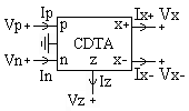
Block diagram of the CDTA. CDTA-block.gif
Block diagram of the CDTA.

Current differencing transconductance amplifier (CDTA) is a new active circuit element.

Electrical network interconnection of electrical components or a model of such an interconnection, consisting of electrical elements

An electrical network is an interconnection of electrical components or a model of such an interconnection, consisting of electrical elements. An electrical circuit is a network consisting of a closed loop, giving a return path for the current. Linear electrical networks, a special type consisting only of sources, linear lumped elements, and linear distributed elements, have the property that signals are linearly superimposable. They are thus more easily analyzed, using powerful frequency domain methods such as Laplace transforms, to determine DC response, AC response, and transient response.

Contents

Properties

The CDTA is not free from parasitic input capacitances and it can operate in a wide frequency range due to current-mode operation. Some voltage and current mode applications using this element have already been reported in literature, particularly from the area of frequency filtering: general higher-order filters, biquad circuits, all-pass sections, gyrators, simulation of grounded and floating inductances and LCR ladder structures. Other studies propose CDTA-based high-frequency oscillators. Nonlinear CDTA applications are also expected, particularly precise rectifiers, current-mode Schmitt triggers for measuring purposes and signal generation, current-mode multipliers, etc.

Parasitic element (electrical networks)

In electrical networks, a parasitic element is a circuit element that is possessed by an electrical component but which it is not desirable for it to have for its intended purpose. For instance, a resistor is designed to possess resistance, but will also possess unwanted parasitic capacitance.

Voltage difference in the electric potential between two points in space

Voltage, electric potential difference, electric pressure or electric tension is the difference in electric potential between two points. The difference in electric potential between two points in a static electric field is defined as the work needed per unit of charge to move a test charge between the two points. In the International System of Units, the derived unit for voltage is named volt. In SI units, work per unit charge is expressed as joules per coulomb, where 1 volt = 1 joule per 1 coulomb. The official SI definition for volt uses power and current, where 1 volt = 1 watt per 1 ampere. This definition is equivalent to the more commonly used 'joules per coulomb'. Voltage or electric potential difference is denoted symbolically by V, but more often simply as V, for instance in the context of Ohm's or Kirchhoff's circuit laws.

Gyrator analog circuit

A gyrator is a passive, linear, lossless, two-port electrical network element proposed in 1948 by Bernard D. H. Tellegen as a hypothetical fifth linear element after the resistor, capacitor, inductor and ideal transformer. Unlike the four conventional elements, the gyrator is non-reciprocal. Gyrators permit network realizations of two-(or-more)-port devices which cannot be realized with just the conventional four elements. In particular, gyrators make possible network realizations of isolators and circulators. Gyrators do not however change the range of one-port devices that can be realized. Although the gyrator was conceived as a fifth linear element, its adoption makes both the ideal transformer and either the capacitor or inductor redundant. Thus the number of necessary linear elements is in fact reduced to three. Circuits that function as gyrators can be built with transistors and op-amps using feedback.

Basic operation

The CDTA element with its schematic symbol in Fig 1 has a pair of low-impedance current inputs and p, n and an auxiliary terminal z, whose outgoing current is the difference of input currents. Here, output terminal currents are equal in magnitude, but flow in opposite directions, and the product of transconductance () and the voltage at the z terminal gives their magnitudes. Therefore, this active element can be characterized with the following equations:

A schematic, or schematic diagram, is a representation of the elements of a system using abstract, graphic symbols rather than realistic pictures. A schematic usually omits all details that are not relevant to the key information the schematic is intended to convey, and may include oversimplified elements in order to make this essential meaning easier to grasp. For example, a subway map intended for passengers may represent a subway station with a dot. The dot is not intended to resemble the actual station at all; instead, it aims to give the viewer information without unnecessary visual clutter. A schematic diagram of a chemical process uses symbols in place of detailed representations of the vessels, piping, valves, pumps, and other equipment that compose the system; in so doing, it emphasizes the functions of these individual elements--and the interconnections among them--and suppresses their particular physical details. In an electronic circuit diagram, the layout of the symbols may not look anything like the circuit as it appears in the physical world: instead of representing the way the circuit looks, the schematic aims to capture, on a more general level, the way it works.

Transconductance, also infrequently called mutual conductance, is the electrical characteristic relating the current through the output of a device to the voltage across the input of a device. Conductance is the reciprocal of resistance.

  1. ,
  2. ,
  3. ,
  4. .

where and is the external impedance connected to z terminal of the CDTA. CDTA can be thought as a combination of a current differencing unit followed by a dual-output operational transconductance amplifier, DO-OTA. Ideally, the OTA is assumed as an ideal voltage-controlled current source and can be described by , where Ix is output current, and denote non-inverting and inverting input voltage of the OTA, respectively. Note that gm is a function of the bias current. When this element is used in CDTA, one of its input terminals is grounded (e.g., ). With dual output availability, condition is assumed.

Related Research Articles

Operational amplifier thid is functional :D DC-coupled high-gain electronic voltage amplifier with a differential input and usually a single-ended outp

An operational amplifier is a DC-coupled high-gain electronic voltage amplifier with a differential input and, usually, a single-ended output. In this configuration, an op-amp produces an output potential that is typically hundreds of thousands of times larger than the potential difference between its input terminals. Operational amplifiers had their origins in analog computers, where they were used to perform mathematical operations in many linear, non-linear, and frequency-dependent circuits.

Negative-feedback amplifier

A Negative-feedback amplifier is an electronic amplifier that subtracts a fraction of its output from its input, so that negative feedback opposes the original signal. The applied negative feedback can improve its performance and reduces sensitivity to parameter variations due to manufacturing or environment. Because of these advantages, many amplifiers and control systems use negative feedback.

Common base

In electronics, a common-base amplifier is one of three basic single-stage bipolar junction transistor (BJT) amplifier topologies, typically used as a current buffer or voltage amplifier.

Impedance matching practice in electronics

In electronics, impedance matching is the practice of designing the input impedance of an electrical load or the output impedance of its corresponding signal source to maximize the power transfer or minimize signal reflection from the load.

Differential amplifier

A differential amplifier is a type of electronic amplifier that amplifies the difference between two input voltages but suppresses any voltage common to the two inputs. It is an analog circuit with two inputs and and one output in which the output is ideally proportional to the difference between the two voltages

Common emitter

In electronics, a common-emitter amplifier is one of three basic single-stage bipolar-junction-transistor (BJT) amplifier topologies, typically used as the voltage amplifier.

Common collector

In electronics, a common collector amplifier is one of three basic single-stage bipolar junction transistor (BJT) amplifier topologies, typically used as a voltage buffer.

Input impedance

The input impedance of an electrical network is the measure of the opposition to current (impedance), both static (resistance) and dynamic (reactance), into the load network that is external to the electrical source. The input admittance (1/impedance) is a measure of the load's propensity to draw current. The source network is the portion of the network that transmits power, and the load network is the portion of the network that consumes power.

A Colpitts oscillator, invented in 1918 by American engineer Edwin H. Colpitts, is one of a number of designs for LC oscillators, electronic oscillators that use a combination of inductors (L) and capacitors (C) to produce an oscillation at a certain frequency. The distinguishing feature of the Colpitts oscillator is that the feedback for the active device is taken from a voltage divider made of two capacitors in series across the inductor.

This article illustrates some typical operational amplifier applications. A non-ideal operational amplifier's equivalent circuit has a finite input impedance, a non-zero output impedance, and a finite gain. A real op-amp has a number of non-ideal features as shown in the diagram, but here a simplified schematic notation is used, many details such as device selection and power supply connections are not shown. Operational amplifiers are optimised for use with negative feedback, and this article discusses only negative-feedback applications. When positive feedback is required, a comparator is usually more appropriate. See Comparator applications for further information.

Current divider

In electronics, a current divider is a simple linear circuit that produces an output current (IX) that is a fraction of its input current (IT). Current division refers to the splitting of current between the branches of the divider. The currents in the various branches of such a circuit will always divide in such a way as to minimize the total energy expended.

In electronics, the Miller effect accounts for the increase in the equivalent input capacitance of an inverting voltage amplifier due to amplification of the effect of capacitance between the input and output terminals. The virtually increased input capacitance due to the Miller effect is given by

A Wilson current mirror is a three-terminal circuit that accepts an input current at the input terminal and provides a "mirrored" current source or sink output at the output terminal. The mirrored current is a precise copy of the input current. It may be used as a Wilson current source by applying a constant bias current to the input branch as in Fig. 2. The circuit is named after George R. Wilson, an integrated circuit design engineer who worked for Tektronix. Wilson devised this configuration in 1967 when he and Barrie Gilbert challenged each other to find an improved current mirror overnight that would use only three transistors. Wilson won the challenge.

Current differencing buffered amplifier

A current differencing buffered amplifier (CDBA) is a multi-terminal active component with two inputs and two outputs and developed by Cevdet Acar and Serdar Özoğuz. Its block diagram can be seen from the figure. It is derived from the current feedback amplifier (CFA).

Operational transconductance amplifier Operational transconductance amplifier

The operational transconductance amplifier (OTA) is an amplifier whose differential input voltage produces an output current. Thus, it is a voltage controlled current source (VCCS). There is usually an additional input for a current to control the amplifier's transconductance. The OTA is similar to a standard operational amplifier in that it has a high impedance differential input stage and that it may be used with negative feedback.

A fully differential amplifier (FDA) is a DC-coupled high-gain electronic voltage amplifier with differential inputs and differential outputs. In its ordinary usage, the output of the FDA is controlled by two feedback paths which, because of the amplifier's high gain, almost completely determine the output voltage for any given input.

The Miller theorem refers to the process of creating equivalent circuits. It asserts that a floating impedance element, supplied by two voltage sources connected in series, may be split into two grounded elements with corresponding impedances. There is also a dual Miller theorem with regards to impedance supplied by two current sources connected in parallel. The two versions are based on the two Kirchhoff's circuit laws.

Transimpedance amplifier amplifier that converts current to voltage

In electronics, a transimpedance amplifier, (TIA) is a current to voltage converter, almost exclusively implemented with one or more operational amplifiers. It is also possible to construct a transimpedance amplifier with discrete components using a Field effect transistor for the gain element. This has been done where a very low noise figure was required. The TIA can be used to amplify the current output of Geiger–Müller tubes, photo multiplier tubes, accelerometers, photo detectors and other types of sensors to a usable voltage. Current to voltage converters are used with sensors that have a current response that is more linear than the voltage response. This is the case with photodiodes where it is not uncommon for the current response to have better than 1% nonlinearity over a wide range of light input. The transimpedance amplifier presents a low impedance to the photodiode and isolates it from the output voltage of the operational amplifier. In its simplest form a transimpedance amplifier has just a large valued feedback resistor, Rf. The gain of the amplifer is set by this resistor and because the amplifier is in an inverting configuration, has a value of -Rf. There are several different configurations of transimpedance amplifiers, each suited to a particular application. The one factor they all have in common is the requirement to convert the low-level current of a sensor to a voltage. The gain, bandwidth, as well as current and voltage offsets change with different types of sensors, requiring different configurations of transimpedance amplifiers.

FET amplifier

A FET amplifier is an amplifier which uses one or more field-effect transistors (FETs). The main advantage of an FET used for amplification is that it has very high input impedance and low output impedance. These are two desirable features for an amplifier.

References