When two particles interact, their mutual cross section is the area transverse to their relative motion within which they must meet in order to scatter from each other. If the particles are hard inelastic spheres that interact only upon contact, their scattering cross section is related to their geometric size. If the particles interact through some action-at-a-distance force, such as electromagnetism or gravity, their scattering cross section is generally larger than their geometric size. When a cross section is specified as a function of some final-state variable, such as particle angle or energy, it is called a differential cross section. When a cross section is integrated over all scattering angles, it is called a total cross section. Cross sections are typically denoted σ (sigma) and measured in units of area.
Torque, moment, or moment of force is the rotational equivalent of linear force. The concept originated with the studies of Archimedes on the usage of levers. Just as a linear force is a push or a pull, a torque can be thought of as a twist to an object. The symbol for torque is typically , the lowercase Greek letter tau. When being referred to as moment of force, it is commonly denoted by M.

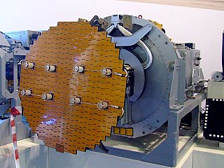
In antenna theory, a phased array usually means an electronically scanned array, a computer-controlled array of antennas which creates a beam of radio waves that can be electronically steered to point in different directions without moving the antennas. In an array antenna, the radio frequency current from the transmitter is fed to the individual antennas with the correct phase relationship so that the radio waves from the separate antennas add together to increase the radiation in a desired direction, while cancelling to suppress radiation in undesired directions. In a phased array, the power from the transmitter is fed to the antennas through devices called phase shifters, controlled by a computer system, which can alter the phase electronically, thus steering the beam of radio waves to a different direction. Since the array must consist of many small antennas to achieve high gain, phased arrays are mainly practical at the high frequency end of the radio spectrum, in the UHF and microwave bands, in which the antenna elements are conveniently small.

In the field of antenna design the term radiation pattern refers to the directional (angular) dependence of the strength of the radio waves from the antenna or other source.
In electromagnetics, an antenna's power gain or simply gain is a key performance number which combines the antenna's directivity and electrical efficiency. In a transmitting antenna, the gain describes how well the antenna converts input power into radio waves headed in a specified direction. In a receiving antenna, the gain describes how well the antenna converts radio waves arriving from a specified direction into electrical power. When no direction is specified, "gain" is understood to refer to the peak value of the gain, the gain in the direction of the antenna's main lobe. A plot of the gain as a function of direction is called the radiation pattern.

A parabolic antenna is an antenna that uses a parabolic reflector, a curved surface with the cross-sectional shape of a parabola, to direct the radio waves. The most common form is shaped like a dish and is popularly called a dish antenna or parabolic dish. The main advantage of a parabolic antenna is that it has high directivity. It functions similarly to a searchlight or flashlight reflector to direct the radio waves in a narrow beam, or receive radio waves from one particular direction only. Parabolic antennas have some of the highest gains, meaning that they can produce the narrowest beamwidths, of any antenna type. In order to achieve narrow beamwidths, the parabolic reflector must be much larger than the wavelength of the radio waves used, so parabolic antennas are used in the high frequency part of the radio spectrum, at UHF and microwave (SHF) frequencies, at which the wavelengths are small enough that conveniently-sized reflectors can be used.

Weather radar, also called weather surveillance radar (WSR) and Doppler weather radar, is a type of radar used to locate precipitation, calculate its motion, and estimate its type. Modern weather radars are mostly pulse-Doppler radars, capable of detecting the motion of rain droplets in addition to the intensity of the precipitation. Both types of data can be analyzed to determine the structure of storms and their potential to cause severe weather.

A Luneburg lens is a spherically symmetric gradient-index lens. A typical Luneburg lens's refractive index n decreases radially from the center to the outer surface. They can be made for use with electromagnetic radiation from visible light to radio waves.
A pulse-Doppler radar is a radar system that determines the range to a target using pulse-timing techniques, and uses the Doppler effect of the returned signal to determine the target object's velocity. It combines the features of pulse radars and continuous-wave radars, which were formerly separate due to the complexity of the electronics.
In electromagnetics and antenna theory, antenna aperture, effective area, or receiving cross section, is a measure of how effective an antenna is at receiving the power of electromagnetic radiation. The aperture is defined as the area, oriented perpendicular to the direction of an incoming electromagnetic wave, which would intercept the same amount of power from that wave as is produced by the antenna receiving it. At any point , a beam of electromagnetic radiation has an irradiance or power flux density which is the amount of power passing through a unit area of one square meter. If an antenna delivers watts to the load connected to its output terminals when irradiated by a uniform field of power density watts per square meter, the antenna's aperture in square meters is given by:

An isotropic radiator is a theoretical point source of electromagnetic or sound waves which radiates the same intensity of radiation in all directions. It has no preferred direction of radiation. It radiates uniformly in all directions over a sphere centred on the source. Isotropic radiators are used as reference radiators with which other sources are compared, for example in determining the gain of antennas. A coherent isotropic radiator of electromagnetic waves is theoretically impossible, but incoherent radiators can be built. An isotropic sound radiator is possible because sound is a longitudinal wave.
Antenna measurement techniques refers to the testing of antennas to ensure that the antenna meets specifications or simply to characterize it. Typical parameters of antennas are gain, radiation pattern, beamwidth, polarization, and impedance.
Monopulse radar is a radar system that uses additional encoding of the radio signal to provide accurate directional information. The name refers to its ability to extract range and direction from a single signal pulse.

In electromagnetics, directivity is a parameter of an antenna or optical system which measures the degree to which the radiation emitted is concentrated in a single direction. It measures the power density the antenna radiates in the direction of its strongest emission, versus the power density radiated by an ideal isotropic radiator radiating the same total power.
Stochastic approximation algorithms are recursive update rules that can be used, among other things, to solve optimization problems and fixed point equations when the collected data is subject to noise. In engineering, optimization problems are often of this type when you do not have a mathematical model of the system but still would like to optimize its behavior by adjusting certain parameters.
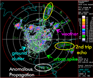
Clutter is a term used for unwanted echoes in electronic systems, particularly in reference to radars. Such echoes are typically returned from ground, sea, rain, animals/insects, chaff and atmospheric turbulences, and can cause serious performance issues with radar systems.
Radar engineering details are technical details pertaining to the components of a radar and their ability to detect the return energy from moving scatterers — determining an object's position or obstruction in the environment. This includes field of view in terms of solid angle and maximum unambiguous range and velocity, as well as angular, range and velocity resolution. Radar sensors are classified by application, architecture, radar mode, platform, and propagation window.
Antenna gain-to-noise-temperature (G/T) is a figure of merit in the characterization of antenna performance, where G is the antenna gain in decibels at the receive frequency, and T is the equivalent noise temperature of the receiving system in kelvins. The receiving system noise temperature is the summation of the antenna noise temperature and the RF chain noise temperature from the antenna terminals to the receiver output.
Moving target indication (MTI) is a mode of operation of a radar to discriminate a target against the clutter. It describes a variety of techniques used to find moving objects, like an aircraft, and filter out unmoving ones, like hills or trees. It contrasts with the modern stationary target indication (STI) technique, which uses details of the signal to directly determine the mechanical properties of the reflecting objects and thereby find targets whether they are moving or not.

Side-looking airborne radar (SLAR) is an aircraft- or satellite-mounted imaging radar pointing perpendicular to the direction of flight. A squinted (nonperpendicular) mode is possible also. SLAR can be fitted with a standard antenna or an antenna using synthetic aperture.

