The IBM System/360 (S/360) is a family of computer systems announced by IBM on April 7, 1964,[1] and delivered between 1965 and 1978.[2] System/360 was the first family of computers designed to cover both commercial and scientific applications and a complete range of sizes from small, entry-level machines to large mainframes. The design distinguished between architecture and implementation, allowing IBM to release a suite of compatible designs at different prices. All but the only partially compatible Model 44 and the most expensive systems use microcode to implement the instruction set, which used 8-bit byte addressing with fixed-point binary, fixed-point decimal and hexadecimalfloating-point calculations. The System/360 family introduced IBM's Solid Logic Technology (SLT), which packed more transistors onto a circuit card, allowing more powerful but smaller computers, but did not include integrated circuits, which IBM considered too immature.[3]
System/360's chief architect was Gene Amdahl and the project was managed by Fred Brooks, responsible to Chairman Thomas J. Watson Jr.[4][5] The commercial release was piloted by another of Watson's lieutenants, John R. Opel, who managed the launch of IBM's System/360 mainframe family in 1964.[6] The slowest System/360 model announced in 1964, the Model 30, could perform up to 34,500 instructions per second, with memory from 8 to 64KB.[7] High-performance models came later. The 1967 IBM System/360 Model 91 could execute up to 16.6 million instructions per second.[8] The larger 360 models could have up to 8MB of main memory,[5] though that much memory was unusual; a large installation might have as little as 256KB of main storage, but 512KB, 768KB or 1024KB was more common. Up to 8 megabytes of slower (8 microsecond) Large Capacity Storage (LCS) was also available for some models.
The IBM 360 was extremely successful, allowing customers to purchase a smaller system knowing they could expand it, if their needs grew, without reprogramming application software or replacing peripheral devices. It influenced computer design for years to come; many consider it one of history's most successful computers. Application-level compatibility (with some restrictions) for System/360 software is maintained to the present day with the IBM Z mainframe servers.
System/360 history
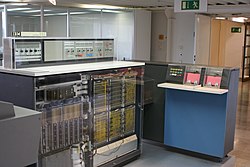
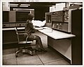
IBM System/360 Model 20 CPU with front panels removed, with IBM 2560 MFCM (Multi-Function Card Machine)IBM System/360 Model 30 CPU (red, middle of picture), tape drives to its left, and disk drives to its right, at the Computer History MuseumIBM System/360 Model 50 CPU, computer operator's console, and peripherals at VolkswagenSystem/360 Model 65 operator's console, with register value lamps and toggle switches (middle of picture) and "emergency pull" switch (upper right)
Background
By the early 1960s, IBM was struggling with the load of supporting and upgrading five separate lines of computers. These were aimed at different market segments and were entirely different from each other. A customer who purchased a machine to handle accounting, such as the IBM 1401, that was now looking for a machine for engineering calculations, such as the IBM 7040, had no reason to select IBM – the 7040 was incompatible with the 1401 and they might as well have been from different companies. Customers were frustrated that major investments, often entirely new machines and programs, were required when seemingly small performance improvements were needed.[9]
In 1961, IBM assembled a task force to chart their developments for the 1960s, known as SPREAD, for Systems Programming, Research, Engineering and Development. In meetings at the New Englander Motor Hotel in Greenwich, Connecticut, SPREAD developed a new concept for the next generation of IBM machines. At the time, new technologies were coming into the market including the introduction of replacement of individual transistors with small-scale integrated circuits and the move to an 8-bit byte from the former 6-bit oriented words. These were going to lead to a new generation of machines, today known as the third generation, from all of the existing vendors.[9]
Where SPREAD differed significantly from previous concepts was what features would be supported. Instead of machines aimed at different market niches, the new concept was effectively the union of all of these designs. A single instruction set architecture (ISA) included instructions for binary, floating-point, and decimal arithmetic, string processing, conversion between character sets (a major issue before the widespread use of ASCII) and extensive support for file handling, among many other features.[9]
This would mean IBM would be introducing yet another line of machines, once again incompatible with their earlier machines. But the new systems would be able to run all of the programs that formerly required different machines. A concern was that there was a risk that their customers, facing the purchase of yet another new and incompatible platform, would simply choose some other vendor. Yet the concept steadily gained support, and six months after being formed, the company decided to implement the SPREAD concept.[9]
Producing a single system design with support for all of these features, at a price acceptable to low-end customers and with a performance level acceptable to high-end customers, would border on impossible. Instead, the SPREAD concept was based on the separation of the defined feature set from its internal operation, with a family of machines with different performance and different internal designs.
Specifically, depending on the machine, some components might not be directly implemented in hardware, and would instead be completed using small programs referred to as microcode or microprograms. These small programs, or subprograms, would be stored in read only memory (ROM)[NB 1] inside the machine. Some models[NB 2] use microcode in the central processing unit (CPU) to implement instructions while others[NB 3] use only hardware. Some models[NB 4] use cycle-stealing microcode in the CPU to implement I/O channels while others[NB 5] use only hardware in separate[NB 6] units. Today this approach is known as microcode.[11]
This meant that a single lineup could have machines tailored to match the price and performance niches that formerly demanded entirely separate computer systems, where software was specific to each system. This flexibility greatly lowered barriers to entry. With most other vendors customers had to choose between machines they might outgrow or machines that were potentially too powerful and thus too costly. In practice, this meant that many companies simply did not buy computers. Now, a customer could purchase a machine that solved a particular requirement, knowing they could switch models as their needs changed, without losing support for the programs they were already running.[9]
For instance, in the case of a firm that purchased an accounting system and was now looking to expand their computer support into engineering, this meant they could develop and test their engineering program on the machine they already used. If they ever needed more performance, they could purchase a machine with floating-point hardware, knowing that nothing else would change, it would simply get faster. Even the same peripherals could be used, allowing, for instance, data from the engineering system to be written to tape and then printed using a high-speed line printer already connected to their accounting system. Or they might replace the accounting system outright with a system with the performance to run both tasks.[9]
The idea that a single design could address all the myriad ways that the machines could be used gave rise to the name, "360" is a reference to 360 degrees in a circle, and circles of machines and components featured prominently in IBM's advertising.[9]
Models
IBM initially announced a series of six computers and forty common peripherals. IBM eventually delivered fourteen models, including rare one-off models for NASA. The least expensive model was the Model 20 with as little as 4096 bytes of core memory, eight 16-bit registers instead of the sixteen 32-bit registers of other System/360 models, and an instruction set that was a subset of that used by the rest of the range.
The initial announcement in 1964 included Models 30, 40, 50, 60, 62, and 70. The first three were low- to middle-range systems aimed at the IBM 1400 series market. All three first shipped in mid-1965. The last three, intended to replace the 7000 series machines, never shipped and were replaced with the 65 and 75, which were first delivered in November 1965, and January 1966, respectively.
Later additions to the low-end included models 20 (1966, mentioned above), 22 (1971), and 25 (1968). The Model 20 had several sub-models; sub-model 5 was at the higher end of the model. The Model 22 was a recycled Model 30 with minor limitations: a smaller maximum memory configuration, and slower I/O channels, which limited it to slower and lower-capacity disk and tape devices than on the 30.
The Model 44 (1966) was a specialized model, designed for scientific computing and for real-time computing and process control, featuring some additional instructions, and with all storage-to-storage instructions and five other complex instructions eliminated.
IBM System/360 Model 91 operator's console at NASA, sometime in the late 1960s.Magnetic-core memory, probably from a 360
A succession of high-end machines included the Model 67 (1966, mentioned below, briefly anticipated as the 64 and 66[12]), 85 (1969), 91 (1967, anticipated as the 92), 95 (1968), and 195 (1971). The 85 design was intermediate between the System/360 line and the follow-on System/370 and was the basis for the 370/165. There was a System/370 version of the 195, but it did not include Dynamic Address Translation.
The implementations differed substantially, using different native data path widths, presence or absence of microcode, yet were extremely compatible. Except where specifically documented, the models were architecturally compatible. The 91, for example, was designed for scientific computing and provided out-of-order instruction execution (and could yield "imprecise interrupts" if a program trap occurred while several instructions were being read), but lacked the decimal instruction set used in commercial applications. New features could be added without violating architectural definitions: the 65 had a dual-processor version (M65MP) with extensions for inter-CPU signalling; the 85 introduced cache memory. Models 44, 75, 91, 95, and 195 were implemented with hardwired logic, rather than microcoded as all other models.
The Model 67, announced in August 1965, was the first production IBM system to offer dynamic address translation (virtual memory) hardware to support time-sharing. "DAT" is now more commonly referred to as an MMU. An experimental one-off unit was built based on a model 40. Before the 67, IBM had announced models 64 and 66, DAT versions of the 60 and 62, but they were almost immediately replaced with the 67 at the same time that the 60 and 62 were replaced with the 65. DAT hardware would reappear in the S/370 series in 1972, though it was initially absent from the series. Like its close relative, the 65, the 67 also offered dual CPUs.
IBM stopped marketing all System/360 models by the end of 1977.[13]
Backward compatibility
IBM's existing customers had a large investment in software that ran on second-generation machines. Several System/360 models had the option of emulating the customer's existing computer using special hardware[14] and microcode, and an emulation program that enabled existing programs to run on the new machine.
Customers initially had to halt the computer and load the emulation program.[15] IBM later added features and modified emulator programs to allow emulation of the 1401, 1440, 1460, 1410 and 7010 under the control of an operating system. The Model 85 and later System/370 maintained the precedent, retaining emulation options and allowing emulators to run under OS control alongside native programs.[16][17]
Successors and variants
System/360 (excepting the Models 20, 44[NB 7] and 67[NB 8]) was replaced with the compatible System/370 range in 1970 and Model 20 users were targeted to move to the IBM System/3. (The idea of a major breakthrough with FS technology was dropped in the mid-1970s for cost-effectiveness and continuity reasons.) Later compatible IBM systems include the 4300 family, the 308x family, the 3090, the ES/9000 and 9672 families (System/390 family), and the IBM Z series.
Computers that were mostly identical or compatible in terms of the machine code or architecture of the System/360 included Amdahl's 470 family (and its successors), Hitachi mainframes, the UNIVAC 9000 series,[18] Fujitsu as the Facom, the RCASpectra 70 series,[NB 9] and the English Electric System 4.[NB 10] The System 4 machines were built under license to RCA. RCA sold the Spectra series to what was then UNIVAC, where they became the UNIVAC Series 70. UNIVAC also developed the UNIVAC Series 90 as successors to the 9000 series and Series 70.[18] The Soviet Union produced a System/360 clone named the ES EVM.[19]
The IBM 5100 portable computer, introduced in 1975, offered an option to execute the System/360's APL.SV programming language through a hardware emulator. IBM used this approach to avoid the costs and delay of creating a 5100-specific version of APL.
Special radiation-hardened and otherwise somewhat modified System/360s, in the form of the System/4 Piavionics computer, are used in several fighter and bomber jet aircraft. In the complete 32-bit AP-101 version, 4 Pi machines were used as the replicated computing nodes of the fault-tolerantSpace Shuttle computer system (in five nodes). The U.S. Federal Aviation Administration operated the IBM 9020, a special cluster of modified System/360s for air traffic control, from 1970 until the 1990s. (Some 9020 software is apparently still used via emulation on newer hardware.[citation needed])
The System/360 introduced a number of industry standards to the marketplace, such as:
The 8-bitbyte (against financial pressure during development to reduce the byte to 4 or 6 bits), rather than adopting the 7030 concept of accessing bytes of variable size at arbitrary bit addresses.
Byte-addressable memory (as opposed to bit-addressable or word-addressable memory)
The System/360 series computer architecture specification makes no assumptions on the implementation itself, but rather describes the interfaces and expected behavior of an implementation.[39][40][41] The architecture describes mandatory interfaces that must be available on all implementations, and optional interfaces. Some aspects of this architecture are:
An interruption mechanism, maskable and unmaskable interruption classes and subclasses
An instruction set. Each instruction is wholly described and also defines the conditions under which an exception is recognized in the form of program interruption.
All models of System/360, except for the Model 20 and Model 44, implemented that specification.
Binary arithmetic and logical operations are performed as register-to-register and as memory-to-register/register-to-memory as a standard feature. If the Commercial Instruction Set option was installed, packed decimal arithmetic could be performed as memory-to-memory with some memory-to-register operations. The Scientific Instruction Set feature, if installed, provided access to four floating-point registers that could be programmed for either 32-bit or 64-bit floating-point operations. The Models 85 and 195 could also operate on 128-bit extended-precision floating-point numbers stored in pairs of floating-point registers, and software provided emulation in other models. The System/360 used an 8-bit byte, 32-bit word, 64-bit double-word, and 4-bit nibble. Machine instructions had operators with operands, which could contain register numbers or memory addresses. This complex combination of instruction options resulted in a variety of instruction lengths and formats.
Memory addressing was accomplished using a base-plus-displacement scheme, with registers 1 through F (15). A displacement was encoded in 12 bits, thus allowing a 4096-byte displacement (0–4095), as the offset from the address put in a base register.
Register 0 could not be used as a base register nor as an index register (nor as a branch address register), as "0" was reserved to indicate an address in the first 4KB of memory, that is, if register 0 was specified as described, the value 0x00000000 was implicitly input to the effective address calculation in place of whatever value might be contained within register 0 (or if specified as a branch address register, then no branch was taken, and the content of register 0 was ignored, but any side effect of the instruction was performed).
This specific behavior permitted initial execution of an interrupt routines, since base registers would not necessarily be set to 0 during the first few instruction cycles of an interrupt routine. It isn't needed for IPL ("Initial Program Load" or boot), as one can always clear a register without the need to save it.
With the exception of the Model 67,[30] all addresses were real memory addresses. Virtual memory was not available in most IBM mainframes until the System/370 series. The Model 67 introduced a virtual memory architecture, which MTS, CP-67, and TSS/360 used—but not IBM's mainline System/360 operating systems.
The System/360 machine-code instructions are 2 bytes long (no memory operands), 4 bytes long (one operand), or 6 bytes long (two operands). Instructions are always situated on 2-byte boundaries.
Operations like MVC (Move-Characters) (Hex: D2) can only move at most 256 bytes of information. Moving more than 256 bytes of data required multiple MVC operations. (The System/370 series introduced a family of more powerful instructions such as the MVCL "Move-Characters-Long" instruction, which supports moving up to 16MB as a single block.)
An operand is two bytes long, typically representing an address as a 4-bit nibble denoting a base register and a 12-bit displacement relative to the contents of that register, in the range 000–FFF (shown here as hexadecimal numbers). The address corresponding to that operand is the contents of the specified general-purpose register plus the displacement. For example, an MVC instruction that moves 256 bytes (with length code 255 in hexadecimal as FF) from base register 7, plus displacement 000, to base register 8, plus displacement 001, would be coded as the 6-byte instruction "D2FF 8001 7000" (operator/length/address1/address2).
The System/360 was designed to separate the supervisor state from the problem state. This provided a basic level of security and recoverability from programming errors. Problem (user) programs could not modify data or program storage associated with the supervisor state. Addressing, data, or operation exception errors made the machine enter the supervisor state through a controlled routine so the operating system could try to correct or terminate the program in error. Similarly, it could recover certain processor hardware errors through the machine check routines.
Peripherals interfaced to the system via channels. A channel is a specialized processor with the instruction set optimized for transferring data between a peripheral and main memory. In modern terms, this could be compared to direct memory access (DMA). The S/360 connects channels to control units with bus and tag cables; IBM eventually replaced these with Enterprise Systems Connection (ESCON) and Fibre Connection (FICON) channels, but well after the S/360 era.
Byte-multiplexor and selector channels
There were initially two types of channels; byte-multiplexer channels (known at the time simply as "multiplexor channels"), for connecting "slow speed" devices such as card readers and punches, line printers, and communications controllers, and selector channels for connecting high speed devices, such as disk drives, tape drives, data cells and drums. Every System/360 (except for the Model 20, which was not a standard 360) has a byte-multiplexer channel and 1 or more selector channels, though the model 25 has just one channel, which can be either a byte-multiplexor or selector channel. The smaller models (up to the model 50) have integrated channels, while for the larger models (model 65 and above) the channels are large separate units in separate cabinets: the IBM 2870 is the byte-multiplexor channel with up to four selector sub-channels, and the IBM 2860 is up to three selector channels.
The byte-multiplexer channel is able to handle I/O to/from several devices simultaneously at the device's highest rated speeds, hence the name, as it multiplexed I/O from those devices onto a single data path to main memory. Devices connected to a byte-multiplexer channel are configured to operate in 1-byte, 2-byte, 4-byte, or "burst" mode. The larger "blocks" of data are used to handle progressively faster devices. For example, a 2501 card reader operating at 600 cards per minute would be in 1-byte mode, while a 1403-N1 printer would be in burst mode. Also, the byte-multiplexer channels on larger models have an optional selector subchannel section that would accommodate tape drives. The byte-multiplexor's channel address was typically "0" and the selector subchannel addresses were from "C0" to "FF." Thus, tape drives on System/360 were commonly addressed at 0C0–0C7. Other common byte-multiplexer addresses are: 00A: 2501 Card Reader, 00C/00D: 2540 Reader/Punch, 00E/00F: 1403-N1 Printers, 010–013: 3211 Printers, 020–0BF: 2701/2703 Telecommunications Units. These addresses are still commonly used in z/VM virtual machines.
System/360 models 40 and 50 have an integrated 1052-7 console that is usually addressed as 01F, however, this was not connected to the byte-multiplexer channel, but rather, had a direct internal connection to the mainframe. The model 30 attached a different model of 1052 through a 1051 control unit. The models 60 through 75 also use the 1052–7.
Cable used as Bus or Tag cable for IBM System/360Bus and tag terminators
Selector channels enabled I/O to high speed devices. These storage devices were attached to a control unit and then to the channel. The control unit let clusters of devices be attached to the channels. On higher speed models, multiple selector channels, which could operate simultaneously or in parallel, improved overall performance.
Control units are connected to the channels with "bus and tag" cable pairs. The bus cables carried the address and data information and the tag cables identified what data was on the bus. The general configuration of a channel is to connect the devices in a chain, like this: Mainframe—Control Unit X—Control Unit Y—Control Unit Z. Each control unit is assigned a "capture range" of addresses that it services. For example, control unit X might capture addresses 40–4F, control unit Y: C0–DF, and control unit Z: 80–9F. Capture ranges had to be a multiple of 8, 16, 32, 64, or 128 devices and be aligned on appropriate boundaries. Each control unit in turn has one or more devices attached to it. For example, you could have control unit Y with 6 disks, that would be addressed as C0-C5.
There are three general types of bus-and-tag cables produced by IBM. The first is the standard gray bus-and-tag cable, followed by the blue bus-and-tag cable, and finally the tan bus-and-tag cable. Generally, newer cable revisions are capable of higher speeds or longer distances, and some peripherals specified minimum cable revisions both upstream and downstream.
The cable ordering of the control units on the channel is also significant. Each control unit is "strapped" as High or Low priority. When a device selection was sent out on a mainframe's channel, the selection was sent from X->Y->Z->Y->X. If the control unit was "high" then the selection was checked in the outbound direction, if "low" then the inbound direction. Thus, control unit X was either 1st or 5th, Y was either 2nd or 4th, and Z was 3rd in line. It is also possible to have multiple channels attached to a control unit from the same or multiple mainframes, thus providing a rich high-performance, multiple-access, and backup capability.
Typically the total cable length of a channel is limited to 200 feet, less being preferred. Each control unit accounts for about 10 "feet" of the 200-foot limit.
Block multiplexer channel
IBM first introduced a new type of I/O channel on the Model 85 and Model 195, the 2880 block multiplexer channel, and then made them standard on the System/370. This channel allowed a device to suspend a channel program, pending the completion of an I/O operation and thus to free the channel for use by another device. A block multiplexer channel can support either standard 1.5MB/s connections or, with the 2-byte interface feature, 3MB/s; the latter use one tag cable and two bus cables. On the S/370 there is an option for a 3.0 MB/s data streaming[42] channel with one bus cable and one tag cable.
The initial use for this was the 2305 fixed-head disk, which has 8 "exposures" (alias addresses) and rotational position sensing (RPS).
Block multiplexer channels can operate as a selector channel to allow compatible attachment of legacy subsystems.[43]
Basic hardware components
A single-width SLT card. Each square metal can contains a hybrid circuit with several transistors.Six-transistor solid logic hybrid circuit with cap offMany SLT cards plugged into an SLT backplane
A number of these SLT modules were then flip chip mounted onto a small multi-layer printed circuit "SLT card". Each card had one or two sockets on one edge that plugged onto pins on one of the computer's "SLT boards" (also referred to as a backplane). This was the reverse of how most other company's cards were mounted, where the cards had pins or printed contact areas and plugged into sockets on the computer's boards.
Up to twenty SLT boards could be assembled side-by-side (vertically and horizontally, max 4 high by 5 wide) to form a "logic gate".[clarification needed] Several gates mounted together constituted a box-shaped "logic frame". The outer gates were generally hinged along one vertical edge so they could be swung open to provide access to the fixed inner gates. The larger machines could have more than one frame bolted together to produce the final unit, such as a multi-frame Central Processing Unit (CPU).
The smaller System/360 models used the Basic Operating System/360 (BOS/360), Tape Operating System (TOS/360), or Disk Operating System/360 (DOS/360, which evolved into DOS/VS, DOS/VSE, VSE/AF, VSE/SP, VSE/ESA, and then z/VSE).
The larger models used Operating System/360 (OS/360). IBM developed several levels of OS/360, with increasingly powerful features: Primary Control Program (PCP), Multiprogramming with a Fixed number of Tasks (MFT), and Multiprogramming with a Variable number of Tasks (MVT). MVT took a long time to develop into a usable system, and the less ambitious MFT was widely used. PCP was used on intermediate machines too small to run MFT well, and on larger machines before MFT was available; the final releases of OS/360 included only MFT and MVT. For the System/370 and later machines, MFT evolved into OS/VS1, while MVT evolved into OS/VS2 (SVS) (Single Virtual Storage), then various versions of MVS (Multiple Virtual Storage) culminating in the current z/OS.
When it announced the Model 67 in August 1965, IBM also announced TSS/360 (Time-Sharing System) for delivery at the same time as the 67. TSS/360, a response to Multics, was an ambitious project that included many advanced features. It had performance problems, was delayed, canceled, reinstated, and finally canceled[NB 14] again in 1971. Customers migrated to CP-67, MTS (Michigan Terminal System), TSO (Time Sharing Option for OS/360), or one of several other time-sharing systems.
CP-67, the original virtual machine system, was also known as CP/CMS. CP/67 was developed outside the IBM mainstream at IBM's Cambridge Scientific Center, in cooperation with MIT researchers. CP/CMS eventually won wide acceptance, and led to the development of VM/370 (Virtual Machine) which had a primary interactive "sub" operating system known as VM/CMS (Conversational Monitoring System). This evolved into today's z/VM.
The Model 20 offered a simplified and rarely used tape-based system called TPS (Tape Processing System), and DPS (Disk Processing System) that provided support for the 2311 disk drive. TPS could run on a machine with 8KB of memory; DPS required 12KB, which was pretty hefty for a Model 20. Many customers ran quite happily with 4KB and CPS (Card Processing System). With TPS and DPS, the card reader was used to read the Job Control Language cards that defined the stack of jobs to run and to read in transaction data such as customer payments. The operating system was held on tape or disk, and results could also be stored on the tapes or hard drives. Stacked job processing became an exciting possibility for the small but adventurous computer user.
A little-known and little-used suite of 80-column punched-card utility programs known as Basic Programming Support (BPS) (jocularly: Barely Programming Support), a precursor of TOS, was available for smaller systems.
Component names
IBM created a new naming system for the new components created for System/360, although well-known old names, like IBM 1403 and IBM 1052, were retained. In this new naming system, components were given four-digit numbers starting with 2. The second digit described the type of component, as follows:
IBM developed a new family of peripheral equipment for System/360, carrying over a few from its older 1400 series. Interfaces were standardized, allowing greater flexibility to mix and match processors, controllers and peripherals than in the earlier product lines.
In addition, System/360 computers could use certain peripherals that were originally developed for earlier computers. These earlier peripherals used a different numbering system, such as the IBM 1403 chain printer. The 1403, an extremely reliable device that had already earned a reputation as a workhorse, was sold as the 1403-N1 when adapted for the System/360.
Also available were optical character recognition (OCR) readers IBM 1287 and IBM 1288 which could read Alpha Numeric (A/N) and Numeric Hand Printed (NHP/NHW) Characters from Cashier's rolls of tape to full legal size pages. At the time this was done with very large optical/logic readers. Software was too slow and expensive at that time.
Models 65 and below sold with an IBM 1052–7 as the console typewriter. The 360/85 with feature 5450 uses a display console that was not compatible with anything else in the line;[44][45] the later 3066 console for the 370/165 and 370/168 use the same basic display design as the 360/85. The IBM System/360 models 91 and 195 use a graphical display similar to the IBM 2250 as their primary console.
Additional operator consoles were also available. Certain high-end machines could optionally be purchased with a 2250 graphical display, costing upwards of US$100,000; smaller machines could use the less expensive 2260 display or later the 3270.
The 156kbit/s 2302 was based on the earlier 1302 and was available as a model 3 with two 112.79MB modules[46]:60 or as a model 4 with four such modules.[46]:60
The 2311, with a removable 1316disk pack, was based on the IBM 1311 and had a theoretical capacity of 7.2MB, although actual capacity varied with record design.[48]:31 (When used with a 360/20, the 1316 pack was formatted into fixed-length 270 byte sectors, giving a maximum capacity of 5.4MB.)
In 1966, the first 2314s shipped. This device had up to eight usable disk drives with an integral control unit; there were nine drives, but one was reserved as a spare. Each drive used a removable 2316 disk pack with a capacity of nearly 28MB. The disk packs for the 2311 and 2314 were physically large by today's standards — e.g., the 1316 disk pack was about 14in (36cm) in diameter and had six platters stacked on a central spindle. The top and bottom outside platters did not store data. Data were recorded on the inner sides of the top and bottom platters and both sides of the inner platters, providing 10 recording surfaces. The 10 read/write heads moved together across the surfaces of the platters, which were formatted with 203 concentric tracks. To reduce the amount of head movement (seeking), data was written in a virtual cylinder from inside top platter down to inside bottom platter. These disks were not usually formatted with fixed-sized sectors as are today's hard drives (though this was done with CP/CMS). Rather, most System/360 I/O software could customize the length of the data record (variable-length records), as was the case with magnetic tapes.
IBM 2314 disk drives and IBM 2540 card reader/punch at the University of Michigan
Some of the most powerful early System/360s used high-speed head-per-track drum storage devices. The 3,500RPM 2301,[49] which replaced the 7320, was part of the original System/360 announcement, with a capacity of 4MB. The 303.8kbit/s IBM 2303[46]:74–76 was announced on January 31, 1966, with a capacity of 3.913MB. These were the only drums announced for System/360 and System/370, and their niche was later filled by fixed-head disks.
The 6,000RPM 2305 appeared in 1970, with capacities of 5MB (2305–1) or 11MB (2305–2) per module.[50][51] Although these devices did not have large capacity, their speed and transfer rates made them attractive for high-performance needs. A typical use was overlay linkage (e.g. for OS and application subroutines) for program sections written to alternate in the same memory regions. Fixed-head disks and drums were particularly effective as paging devices on the early virtual memory systems. The 2305, although often called a "drum" was actually a head-per-track disk device, with 12 recording surfaces and a data transfer rate up to 3MB/s.
Rarely seen was the IBM 2321 Data Cell,[52] a mechanically complex device that contained multiple magnetic strips to hold data; strips could be randomly accessed, placed upon a cylinder-shaped drum for read/write operations; then returned to an internal storage cartridge. The IBM Data Cell [noodle picker] was among several IBM trademarked "speedy" mass online direct-access storage peripherals (reincarnated in recent years as "virtual tape" and automated tape librarian peripherals). The 2321 file had a capacity of 400MB, at the time when the 2311 disk drive only had 7.2MB. The IBM Data Cell was proposed to fill cost/capacity/speed gap between magnetic tapes—which had high capacity with relatively low cost per stored byte—and disks, which had higher expense per byte. Some installations also found the electromechanical operation less dependable and opted for less mechanical forms of direct-access storage.
The Model 44 was unique in offering an integrated single-disk drive as a standard feature. This drive used the 2315 "ramkit" cartridge and provided 1,171,200 bytes of storage.[31]:11
Magnetic Tape drives
IBM 2401 tape drives
The 2400-series of 1/2" magnetic tape units consisted of the 2401 and 2402 Models 1-6 Magnetic Tape Units, the 2403 Models 1-6 Magnetic Tape Unit and Control, the 2404 Models 1-3 Magnetic Tape Unit and Control, and the 2803/2804 Models 1 and 2 Tape Control Units.[53] The later 2415 Magnetic Tape Unit and Control, introduced in 1967 contained two, four, or six tape drives and a control in a single unit, and was slower and cheaper.[54] The 2415 drives and control were not marketed separately.[55] With System/360, IBM switched from IBM 7-track to 9-track tape format. Some 2400-series drives could be purchased that read and wrote 7-track tapes for compatibility with the older IBM 729 tape drives. In 1968, the IBM 2420 tape system was released, offering much higher data rates, self-threading tape operation and 1600bpi packing density.[56] It remained in the product line until 1979.[57]
Punched card devices included the 2501 card reader and the 2540 card reader punch. Virtually every System/360 had a 2540. The 2560 MFCM ("Multi-Function Card Machine") reader/sorter/punch, listed above, was for the Model 20 only. It was notorious for reliability problems (earning humorous acronyms often involving "...Card Muncher" or "Mal-Function Card Machine").
A paper tape reader, the IBM 2671, was introduced in 1964. It had a rated speed of 1,000 cps. There were also a paper tape reader and paper tape punch from an earlier era, available only as RPQs (Request Price Quotation). The 1054 (reader) and 1055 (punch), which were carried forward (like the 1052 console typewriter) from the IBM 1050 Teleprocessing System. All these devices operated at a maximum of 15.5 characters per second. The paper tape punch from the IBM 1080 System was also available by RPQ, but at a prohibitively expensive price.
Optical character recognition (OCR) devices 1287 and later the 1288 were available on the 360's. The 1287 could read handwritten numerals, some OCR fonts, and cash register OCR paper tape reels. The 1288 'page reader' could handle up to legal size OCR font typewritten pages, as well as handwritten numerals. Both of these OCR devices employed a 'flying spot' scanning principle, with the raster scan provided by a large CRT, and the reflected light density changes were picked up by a high gain photomultiplier tube.
Magnetic ink character recognition (MICR) was provided by the IBM 1412 and 1419 cheque sorters, with magnetic ink printing (for cheque books) on 1445 printers (a modified 1443 that used an MICR ribbon). 1412/1419 and 1445 were mainly used by banking institutions.
Remaining machines
Despite having been sold or leased in very large numbers for a mainframe system of its era, only a few of System/360 computers remain—mainly as non-operating property of museums or collectors. Examples of existing systems include:
The KCG Computer Museum of Kyoto Computer Gakuin, Japan's first computer school in town,[clarification needed] has an IBM System/360 Model 40 on display.[59]
Two Model 20 processors along with numerous peripherals (forming at least one complete system) located in Nürnberg, Germany were purchased on eBay in April/May 2019 for €3710 by two UK enthusiasts who, over the course of some months, moved the machine to Creslow Park in Buckinghamshire, United Kingdom. The system was in a small, abandoned building left untouched for decades, and apparently had been used in that building since all peripherals were still fully wired and interconnected.[60] As of September 2024 the systems have been moved on a long-term loan basis to the System Source Computer Museum in Hunt Valley, Maryland, USA for display and restoration.[61]
↑IBM did provide upgrades to CP-67/CMS and TSS/360 that ran on S/370, but without 32-bit addressing.
↑The RCA Spectra 70 had radically different architecture for interrupts and I/O. There were compatibility packages to allow operating systems for System/360 to run on a Spectra/70 and vice versa.
↑Intended for real-time processing, the English Electric System 4 employed four processor states, each with its own set of general-purpose registers. Instructions available in the user state were identical to the System/360. The other states were entered according to the class or severity of interrupt. The fourth (the highest) state was entered when power failure was imminent, and enabled the processor to shut itself down in an orderly fashion.
↑Performance calculated (not measured) based on a mix of instructions typical of scientific applications ("Gibson Mix") with the results in kilo Instructions Per Second (kIPS) per Longbottom, Roy. "Computer Speeds From Instruction Mixes – pre-1960 to 1971". Retrieved October 12, 2014. except for M95 and M195. The latter based upon estimates of performance relative to M65 from Pugh.
↑In System/360 architecture bit 12 of the program status word (PSW) controlled selection between the EBCDIC or a then proposed ASCII-8 mode signed decimal data. The proposed ASCII-8 ANSI standard was in the approval process when System/360 was announced but it was subsequently rejected and no ASCII peripheral devices were made available. This capability was not included in System/370; bit 12 of the PSW was redefined to switch between System/360 (BC mode) and System/370 (EC mode) PSW format.
↑However, it could still be ordered, and a TSS/370 PRPQ was available on the S/370 and went through multiple releases.
12"System/360 Announcement" (Press release). IBM Data Processing Division. April 7, 1964. IBM-PR360. Archived from the original on January 14, 2005. ...machine cycle time ... ranges from one millionth-of-a-second to only 200 billionths-of-a-second. ... memory capacity ranges from 8,000 characters of information to more than 8,000,000.
↑Tucker, S. G. (1967). "Microprogram control for SYSTEM/360". IBM Systems Journal. 6 (4): 222–241. doi:10.1147/sj.64.0222.
↑"System/360 Time Sharing Computers". DIGITAL COMPUTER NEWSLETTER. Vol.17, no.3. Office of Naval Research, Mathematical Sciences Division. July 1965. pp.5–6.
↑Elliott, Jim (2010). "IBM Mainframes – 45+ Years of Evolution"(PDF). IBM Canada Ltd. p.17. shows the announcement, ship and withdrawal dates for all S/360 models other than the transient models 64 and 66
↑System/370 Model 165 Theory of Operation (Volume 8) 709/7090/7094/7094-II Compatibility Feature. Second Edition. IBM. February 1971. SY77-6835-0.
↑System/360, Model 30 1401 Compatibility Feature(PDF). IBM. April 1964. A24-3255-1. Mode status (System/360, Model 30, mode or 1401 compatibility mode) is set during the read-in of the compatibility initialization deck.
↑Emulating the IBM 7094 on the IBM Models 85 and 165 using OS/360 - Program Number for M/85: 360C-EU-734 - Program Number for M/165: 360C-EU-740 - OS Release 20 (Thirded.). IBM. November 1971. GC27-6951-2.
↑7094 OS Emulator on Models 165/168 Reference - Program Number for OS/MFT and OS/MVT - 360C-EU-740 and Program Number for OS/VS1 and OS/VS2 5744-AM1 (Firsted.). IBM. GC27-6983-0.
Macdonald, Neil (May 1964). "The IBM System/360"(PDF). Computers and Automation. See also Microelectronic Circuitry of the IBM System/360, p. 37: 32–34, 36-36A, 36D, 40.
Davis, E. M.; Harding, W. E.; Schwartz, R. S.; Corning, J. J. (1964). "Solid Logic Technology: Versatile, High-Performance Microelectronics". IBM Journal of Research and Development. 8 (2): 102–114. doi:10.1147/rd.82.0102. S2CID13288023.
Stevens, W. Y. (1964). "The structure of System/360, Part II: System implementations". IBM Systems Journal. 3 (2): 136–143. doi:10.1147/sj.32.0136.
Amdahl, G. M. (1964). "The structure of System/360, Part III: Processing unit design considerations". IBM Systems Journal. 3 (2): 144–164. doi:10.1147/sj.32.0144.
Padegs, A. (1964). "The structure of System/360, Part IV: Channel design considerations". IBM Systems Journal. 3 (2): 165–179. doi:10.1147/sj.32.0165.
Blaauw, G. A. (1964). "The structure of System/360, Part V: Multisystem organization". IBM Systems Journal. 3 (2): 181–195. doi:10.1147/sj.32.0181.
Tucker, S. G. (1967). "Microprogram control for System/360". IBM Systems Journal. 6 (4): 222–241. doi:10.1147/sj.64.0222.
This page is based on this Wikipedia article Text is available under the CC BY-SA 4.0 license; additional terms may apply. Images, videos and audio are available under their respective licenses.