The paraformer is a particular type of transformer. It transfers the power from primary to secondary windings not by mutual inductance coupling but by a variation of a parameter in its magnetic circuit. First described by Wanlass, et al., 1968.

A transformer is a static electrical device that transfers electrical energy between two or more circuits. A varying current in one coil of the transformer produces a varying magnetic flux, which, in turn, induces a varying electromotive force across a second coil wound around the same core. Electrical energy can be transferred between the two coils, without a metallic connection between the two circuits. Faraday's law of induction discovered in 1831 described the induced voltage effect in any coil due to changing magnetic flux encircled by the coil.

Electric power is the rate, per unit time, at which electrical energy is transferred by an electric circuit. The SI unit of power is the watt, one joule per second.
A magnetic circuit is made up of one or more closed loop paths containing a magnetic flux. The flux is usually generated by permanent magnets or electromagnets and confined to the path by magnetic cores consisting of ferromagnetic materials like iron, although there may be air gaps or other materials in the path. Magnetic circuits are employed to efficiently channel magnetic fields in many devices such as electric motors, generators, transformers, relays, lifting electromagnets, SQUIDs, galvanometers, and magnetic recording heads.
Assuming Faraday's law of induction,

it is possible to obtain a voltage at the secondary winding terminals also thanks to a variation of the inductance, so that

Voltage, electric potential difference, electric pressure or electric tension is the difference in electric potential between two points. The difference in electric potential between two points in a static electric field is defined as the work needed per unit of charge to move a test charge between the two points. In the International System of Units, the derived unit for voltage is named volt. In SI units, work per unit charge is expressed as joules per coulomb, where 1 volt = 1 joule per 1 coulomb. The official SI definition for volt uses power and current, where 1 volt = 1 watt per 1 ampere. This definition is equivalent to the more commonly used 'joules per coulomb'. Voltage or electric potential difference is denoted symbolically by ∆V, but more often simply as V, for instance in the context of Ohm's or Kirchhoff's circuit laws.

This can be accomplished by for example modulating the saturation of the core by means of an applied variable magnetic field. It works even if primary and secondary windings magnetic coupling is zero (when the fluxes are mutually orthogonal) (Burian 1972, p. 278).

Seen in some magnetic materials, saturation is the state reached when an increase in applied external magnetic field H cannot increase the magnetization of the material further, so the total magnetic flux density B more or less levels off. Saturation is a characteristic of ferromagnetic and ferrimagnetic materials, such as iron, nickel, cobalt and their alloys.
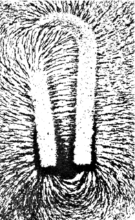
A magnetic field is a vector field that describes the magnetic influence of electric charges in relative motion and magnetized materials. Magnetic fields are observed in a wide range of size scales, from subatomic particles to galaxies. In everyday life, the effects of magnetic fields are often seen in permanent magnets, which pull on magnetic materials and attract or repel other magnets. Magnetic fields surround and are created by magnetized material and by moving electric charges such as those used in electromagnets. Magnetic fields exert forces on nearby moving electrical charges and torques on nearby magnets. In addition, a magnetic field that varies with location exerts a force on magnetic materials. Both the strength and direction of a magnetic field vary with location. As such, it is an example of a vector field.

In physics, specifically electromagnetism, the magnetic flux through a surface is the surface integral of the normal component of the magnetic field B passing through that surface. The SI unit of magnetic flux is the weber (Wb), and the CGS unit is the maxwell. Magnetic flux is usually measured with a fluxmeter, which contains measuring coils and electronics, that evaluates the change of voltage in the measuring coils to calculate the magnetic flux.

An inductor, also called a coil, choke, or reactor, is a passive two-terminal electrical component that stores energy in a magnetic field when electric current flows through it. An inductor typically consists of an insulated wire wound into a coil around a core.

Alternating current (AC) is an electric current which periodically reverses direction, in contrast to direct current (DC) which flows only in one direction. Alternating current is the form in which electric power is delivered to businesses and residences, and it is the form of electrical energy that consumers typically use when they plug kitchen appliances, televisions, fans and electric lamps into a wall socket. A common source of DC power is a battery cell in a flashlight. The abbreviations AC and DC are often used to mean simply alternating and direct, as when they modify current or voltage.

A rectifier is an electrical device that converts alternating current (AC), which periodically reverses direction, to direct current (DC), which flows in only one direction.
In electromagnetism and electronics, inductance describes the tendency of an electrical conductor, such as coil, to oppose a change in the electric current through it. The change in current induces a reverse electromotive force (voltage). When an electric current flows through a conductor, it creates a magnetic field around that conductor. A changing current, in turn, creates a changing magnetic field, the surface integral of which is known as magnetic flux. From Faraday's law of induction, any change in magnetic flux through a circuit induces an electromotive force (voltage) across that circuit, a phenomenon known as electromagnetic induction. Inductance,
, is defined as the ratio between this induced voltage,
, and the rate of change of the current
in the circuit.

A Rogowski coil, named after Walter Rogowski, is an electrical device for measuring alternating current (AC) or high-speed current pulses. It consists of a helical coil of wire with the lead from one end returning through the centre of the coil to the other end, so that both terminals are at the same end of the coil. The whole assembly is then wrapped around the straight conductor whose current is to be measured. There is no metal (iron) core. The winding density, the diameter of the coil and the rigidity of the winding are critical for preserving immunity to external fields and low sensitivity to the positioning of the measured conductor.

A gyrator is a passive, linear, lossless, two-port electrical network element proposed in 1948 by Bernard D. H. Tellegen as a hypothetical fifth linear element after the resistor, capacitor, inductor and ideal transformer. Unlike the four conventional elements, the gyrator is non-reciprocal. Gyrators permit network realizations of two-(or-more)-port devices which cannot be realized with just the conventional four elements. In particular, gyrators make possible network realizations of isolators and circulators. Gyrators do not however change the range of one-port devices that can be realized. Although the gyrator was conceived as a fifth linear element, its adoption makes both the ideal transformer and either the capacitor or inductor redundant. Thus the number of necessary linear elements is in fact reduced to three. Circuits that function as gyrators can be built with transistors and op-amps using feedback.
The Ćuk converter is a type of DC/DC converter that has an output voltage magnitude that is either greater than or less than the input voltage magnitude. It is essentially a boost converter followed by a buck converter with a capacitor to couple the energy.
An autotransformer is an electrical transformer with only one winding. The "auto" prefix refers to the single coil acting alone, not to any kind of automatic mechanism. In an autotransformer, portions of the same winding act as both the primary and secondary sides of the transformer. In contrast, an ordinary transformer has separate primary and secondary windings which are not electrically connected.

A flyback transformer (FBT), also called a line output transformer (LOPT), is a special type of electrical transformer. It was initially designed to generate high voltage sawtooth signals at a relatively high frequency. In modern applications, it is used extensively in switched-mode power supplies for both low (3 V) and high voltage supplies.
Leakage inductance derives from the electrical property of an imperfectly-coupled transformer whereby each winding behaves as a self-inductance in series with the winding's respective ohmic resistance constant. These four winding constants also interact with the transformer's mutual inductance. The winding leakage inductance is due to leakage flux not linking with all turns of each imperfectly-coupled winding.

A charge pump is a kind of DC to DC converter that uses capacitors for energetic charge storage to raise or lower voltage. Charge-pump circuits are capable of high efficiencies, sometimes as high as 90–95%, while being electrically simple circuits.

A blocking oscillator is a simple configuration of discrete electronic components which can produce a free-running signal, requiring only a resistor, a transformer, and one amplifying element. The name is derived from the fact that the transistor is cut-off or "blocked" for most of the duty-cycle, producing periodic pulses. The non-sinusoidal output is not suitable for use as a radio-frequency local oscillator, but it can serve as a timing generator, to power lights, LEDs, Elwire, or small neon indicators. The simple tones are also sufficient for applications such as alarms or a Morse code practice device. Some cameras use a blocking oscillator to strobe the flash prior to a shot to reduce the red-eye effect.
A boost converter is a DC-to-DC power converter that steps up voltage from its input (supply) to its output (load). It is a class of switched-mode power supply (SMPS) containing at least two semiconductors and at least one energy storage element: a capacitor, inductor, or the two in combination. To reduce voltage ripple, filters made of capacitors are normally added to such a converter's output and input.

A buck converter is a DC-to-DC power converter which steps down voltage from its input (supply) to its output (load). It is a class of switched-mode power supply (SMPS) typically containing at least two semiconductors and at least one energy storage element, a capacitor, inductor, or the two in combination. To reduce voltage ripple, filters made of capacitors are normally added to such a converter's output and input.

A variety of types of electrical transformer are made for different purposes. Despite their design differences, the various types employ the same basic principle as discovered in 1831 by Michael Faraday, and share several key functional parts.
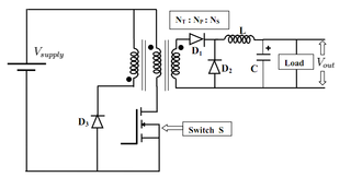
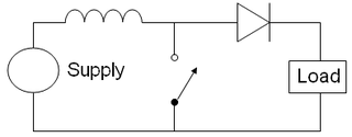
The forward converter is a DC/DC converter that uses a transformer to increase or decrease the output voltage and provide galvanic isolation for the load. With multiple output windings, it is possible to provide both higher and lower voltage outputs simultaneously.

An induction regulator is an alternating current electrical machine, somewhat similar to an induction motor, which can provide a continuously variable output voltage. The induction regulator was an early device used to control the voltage of electric networks. Since the 1930s it has been replaced in distribution network applications by the tap transformer. Its usage is now mostly confined to electrical laboratories, electrochemical processes and arc welding. With minor variations, its setup can be used as a phase-shifting power transformer.
A loss free resistor (LFR) is a resistor that does not lose energy. The first implementation is due to Singer and it has been implemented in various settings.
A severity factor is established as a coefficient to assess the dielectric severity supported by a transformer winding considering the incoming transient overvoltage. It determines the safety margin regarding to the standard acceptance tests either in the frequency or time domain.