^ 3) According to SBB type sketches. In reality, it is probably 19,800 mm, since wooden sleepers with a thickness of approximately 170 mm were added to the buttress beams during the reconstruction.
The Ce 6/8 II (later becoming Be 6/8 II) are electric locomotives of the Swiss Federal Railways (SBB), which were primarily used on the Gotthard Railway in front of freight trains and were in service until the 1980s. Of the 33 locomotives built from 1919 onwards, seven are preserved. The Ce 6/8II, along with the Ce6/8III of similar design but developed a little later, was given the internationally known nickname Crocodile.
History
On 30 June 1917, the SBB put out a tender for four prototype locomotives: Fb 2x2/3 11301, Fb 2x2/3 11302, Fc 2x3/4, and Fb 3/5 11201. These four locomotives, being prototypes, were to be extensively tested after their delivery.
The electrification of the Gotthard Railway was planned for completion in 1920. Coal shortages resulting from World War I progressively forced the SBB to reduce schedules to the point where, in the autumn of 1918, only milk trains ran on Sundays.[1]:5 Under pressure to exploit the new infrastructure, in the spring of 1918 (10 months before delivery of the prototypes), the SBB therefore ordered the heavy mountain freight locomotives Ce 6/8II 14251–14260 with the wheel arrangement 1′C+C1′ in addition to the heavy mountain passenger locomotives Be 4/6 12303–12312 and Be 4/7 12501–12506. Because certain kinematic problems were feared with the Swiss Locomotive and Machine Works' rod drive design on the test locomotive Fc 2x3/4, the SBB followed the industry's recommendation for a locomotive with a 1′C+C1′ wheel arrangement instead of the (1′C)(C1′) bogie arrangement with a one-piece locomotive body. A different rod drive was also proposed. The locomotive no longer consisted of a single body, but of three parts: two narrow front sections and a standard-width center section, which were connected by hinges.
Specifications and contract award
The SBB required the industry to comply with the following specifications:[2][1]:64
The locomotives must be able to travel the route between Goldau and Chiasso twice within 28 hours, with a stopping time of 15 minutes at each terminal station, with a trailer load of 860 t. Pushing is permitted on gradients greater than 10‰.
On the Bellinzona–Chiasso line, a trailer load of 625 t must be capable of being pulled single-unit (single traction). The electrical components must not exceed the values specified in the relevant American standards during any operation and for the entire duration of the operation.
On a steep section (ramp) of 26‰, a locomotive must be capable of hauling a trailer load of 430 t at 35 km/h and 300 t at 50km/h. On a 10‰ gradient, a locomotive must be capable of hauling a trailer load of 300 t at 65km/h.
The locomotives must be capable of delivering 20 percent more power for 15 minutes on 26‰ gradients. The starting tractive effort must be designed so that a train of 430 t / 300 t can be accelerated to a speed of 35km/h or 50km/h in a maximum of four minutes.
In contrast to the four test locomotives, the industrial bidders proposed a completely different design to SBB. The locomotive was to consist of two narrow, low front bodies and a body of standard width and height between them, which were connected by hinges. This articulation marked a departure from the test locomotives under construction with a frame or bogies, but it was known from steam locomotive designs such as the Garratt locomotives. Initial experiences[3] with the test locomotive Fc 2x3/3 of the Bern-Lötschberg-Simplon Railway may have led to this decision.
The Mechanical Part
Chassis
Each of the two front sections contains three drive axles coupled with coupling rods and one carriage axle in a Bissel axle. The middle drive axle of each section has a lateral displacement of 25 mm for better cornering characteristics. The carriage axles can move 83 mm to either side.[1]:72 The drive axles are cushioned by leaf springs on the frames of the front sections, with compensation levers[4] installed between the drive axles and the adjacent carriage axle to compensate for the axle pressure.
Cross coupling (red) to steer axles within a bogie can also be applied between linked motor frames (blue)
The traction and thrust forces are transmitted from the driving axles to the frame of the front end. From there, the forces are transmitted to the drawbar and buffers. The forces are also transmitted from one motor frame to the other via a spring-loaded close coupling. Thus, the central body does not serve to transmit power from one motor frame to the other (see Locomotive body, below). The close coupling also acts as a cross coupling (figure), thereby particularly improving the entry of the trailing motor frame into curves.[1]
Drive
Rod drive with triangular frame. Jackshaft on the left, dead-shaft on the right.
Two drive motors are installed in each frame of the front end between the first and second drive axles. Each of the two motors drives common gears via spring-loaded pinions on both sides, which are located on the jackshaft, also located between the first and second drive axles. From the jackshaft, the transmission is via a triangular frame, which is supported by cranks on a pendulum-sprung dead-shaft, via a sliding bearing to the first drive axle. From a pivot point on the triangular frame, the drive power is transmitted to the second and third drive axles via coupling rods. The springs of the dead-shaft were removed in 1945, as the resulting horizontal forces proved to be low. In the successor series, the Ce 6/8III, the drive system was replaced by the Winterthur type inclined rod drive, which is one of the main external distinguishing features between the two types.[1]:65
Locomotive body
The locomotive body is constructed in three parts. The two outer parts (front sections) are firmly connected to the drive frames. The body itself in the center is supported by spherical pivots on pivot pins in the drive frames. One pivot is fixed, the other is longitudinally movable so that no tensile and compressive forces are transmitted via the central body (see traction power transmission, above). Furthermore, spring-loaded pressure supports are arranged on both sides of the pivots.[2]
The driver's cab had a window and two louvered ventilators on one side, and a blank metal wall on the other. The road number plate on the windowed side was lower than its counterpart.[2]
Air brake and air supply
The locomotives are equipped with a Westinghouse compressed air double brake. This, like the handbrake, acts on the two brake shoes on each driving axle. The trailing axles are not braked. Stopex brake slack adjusters were installed between 1959 and 1963.[1]:65–66 There are four air-operated sandboxes per power unit.
The compressors for providing high-pressure air for braking and engine operation were located under the hoods at the front of each bogie. An air storage tank was also located there.[2]
The Electrical Part
Main Circuit
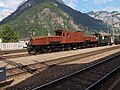
Ce 6/8 II 14274 in the summer of 1963 with a through freight train at Yverdon station.
The Ce 6/8IIs were mechanically more or less identical. Electrically, however, there were significant differences.
The two pantographs and the lightning protection coil were located on the middle car body. The electro-pneumatic throttle control ("jumper control") was located in the box on the windowless side. The transformer was located in a shaft in the middle of the box. The lightning protection coil was later removed.[1]:66
To cool the transformer oil, the transformer tank (housing) of locomotives 14251–14273 (except 14264) was provided with external fins. Two groups of fans were located beneath the floor frame. These blew cooling air from bottom to top, past the fins, through the shaft.[1]:66
Locomotives 14264 and 14274–14283 had transformer tanks with smooth outer walls. The oil was forced through the oil cooler by a separate oil pump.[1]:66
The transformers of locomotives 14251–14273 were switchable upon delivery for operation with 7,500 V overhead line voltage instead of 15,000 V. This was necessary because the Gotthard Railway was initially operated at only half the overhead line voltage. This was intended to prevent arcing on the insulators, which were still sooty from the steam operation.[1]:66
On the low-voltage side (secondary side), the transformers had two step windings, each with eleven taps ranging from 113 V to 567 V. The taps of these two windings had opposite voltages. Via two step switches, voltages of up to 1,100 V could be supplied to the parallel traction motor groups in the two drive frames in 20 or 23 steps. Since the two traction motors of a power unit were connected in series, the maximum voltage per motor was approximately 550 V.[1]:66
Main transformer of locomotives 14251–14273, excluding 14264
Oil main switch, lifted out of the case
The tap changers were located on both sides of the transformer. They were separated from the driver's cabs only by sheet metal partitions. The locomotive crew therefore didn't exactly have the quietest workplace.[1]:67
Locomotives 14251–14255 and 14258–14260 had roller switches similar to the test locomotive Fb 2x2/3 11301. They were driven by electric servomotors. Operation was via a control panel or a small, vertical handwheel on the driver's cab.[1]:67
The roller switch was cumbersome, so locomotives 14256, 14257, and 14261–14283 were fitted with electrically operated lever switches. On locomotives 14261–14265, each lever switch had a servomotor. Locomotives 14266–14283 had only one servomotor, as the two step switches were mechanically connected. Operation was via a horizontal handwheel on the driver's cab. This allowed 20 steps (14261–14265) or 23 steps (14266–14283) to be switched.[1]:67
A completely different concept was chosen for locomotives 14256 and 14257. Here, too, the two step switches were mechanically coupled. Switching on and off in stages was done with a huge, vertical handwheel on the driver's cab. Only for switching to zero was there a small lever on the driver's cab that activated a servo motor. Operating these two machines was quite a physical effort.[1]:67
Step switch as a roller switch driven by a servo motor
Step switch as a lever switch
Each of the two front sections housed two traction motors and the electro-pneumatically operated reversing switches.[1]:67–68
Installed traction motor group with fan and mounted reversing switches
Removed traction motor group seen from the other side
Electric Regenerative Brake
The Ce 6/8 II locomotives were equipped with an electric regenerative brake, which fed the electrical energy of the traction motors acting as generators back into the overhead line during braking. Inductive shunts and brake chokes were used as additional elements in the circuit, while the resistive reversing pole shunts required during driving were not used in the braking circuit. To initiate electric braking, the tap changer first had to be decelerated to zero. The reversing switch could then be switched from "Forward" (V) to "Brake Forward" (BV), and the tap changer could be switched back on.[1]:68
Traction motor circuit of the Crocodile locomotive. Drive left, brake right
Driver's desk of the Crocodile locomotive. Top left: pantograph, bottom left: main switch, center: reversing switch with the positions R (reverse), 0, V (forward), and BV (brake forward), right: handwheel for operating the step switch
Auxiliary Systems
Motor/generator for the control power supply
The following auxiliary systems were supplied with 220 V from the transformer:[1]:68
One piston compressor in each front section
One fan for each of the two traction motor groups
Two fans for the transformer (14251–14263, 14265–14273) or one motor to drive the oil pump and fan for the oil cooler (14264, 14274–14283)
36 V motor-generator for battery charging and locomotive control circuits, output approx. 1.5kW
Driver's cab heating
Foot warmers
Oil heating plate (driver's cab I)
Each front section had a permanently installed lamp. A hatch was located to the left above the driver's desk. If you opened it, you could see, hear and smell whether everything was OK under the front hoods.[1]:68–69
Train heating
Single-pole oil switch for the train busbar.
The power for the train heating was taken from the transformer. On the first ten locomotives, 800 V, 1,000 V, and 1,200 V could be switched, although the 1,200 V could only be used when stationary. On the other locomotives, only 800 V and 1,000 V were available. The 1,200 V stage was later removed from the first ten locomotives. Before 1950, the 800 V stage was also removed from all locomotives.[1]:69
Operational Use
After delivery in 1919, they operated the Bern–Thun–Spiez line, as this was the only electrified line operated by the SBB. The Crocodiles operated at a voltage of 7,500 V instead of the later standard 15,000 V. This was necessary at the beginning because the pollution of the insulators caused by steam locomotives did not yet allow for higher voltages.[2]
With the electrification of the Gotthard line from October 1920, the Crocodiles were primarily used for Gotthard traffic. They replaced the steam locomotives SBB C 5/6, which were only three to six years old.
The Crocodiles were used in freight traffic throughout Switzerland.
From 1941 onwards, the locomotives were extensively rebuilt. In this context, the maximum speed was increased from 65 km/h to 75km/h; the locomotives were therefore given the designation Be 6/8II and numbered starting at 13,000.[1]:69
After the Second World War and with the advent of the Ae 6/6, which was henceforth responsible for the Gotthard, the Crocodiles were increasingly used in lowland areas. In the 1970s and 1980s, they were primarily used in front of gravel trains, sugar beet trains, and in shunting.[2]
Retirement and Preservation
The first Ce 6/8 II locomotives were decommissioned in 1965. Crocodiles modified into shunting vehicles, which at the end of their service life were used in the Rhine ports of Basel, operated until 1986.[2]
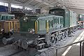
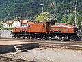
Ce 6/8II No. 14270 as a technical monument in Erstfeld (2011)
Ce 6/8II No. 14253 in Erstfeld
Ce 6/8II No. 14253 (front view)
Ce 6/8II No. 14253 in Erstfeld, with light steel carriages
Ce 6/8II No. 14282 in the Sinsheim Auto and Technology Museum
See also
Christian Zellweger (SBB Historic) (2005). Crocodile, Queen of the Electric Locomotives. AS Verlag & Buchkonzept AG, Zurich. ISBN3-909111-19-X.
Hans-Bernhard Schönborn (1999). Crocodiles, Legend on Rails: Standard and Narrow Gauge. Geramond Verlag, Munich. ISBN3-932785-54-1.
Jeanmaire dit Quartier, Claude (1979). Die elektrischen und Diesel-Triebfahrzeuge schweizerischer Eisenbahnen, Die Lokomotiven der Schweizerischen Bundesbahnen (SBB) [The electric and diesel locomotives of Swiss Railways; The locomotives of the Swiss Federal Railways (SBB)] (in German). Verlag Eisenbahn. ISBN3-85649-036-1.
[s.n.] (1920). "1C+C1 Güterzug-Lokomotiven für die Gotthardlinie der S.B.B. (1C+C1 Freight Locomotives for the Gotthard Line of the SBB)". Schweizerische Bauzeitung (in German). 75 (21). doi:10.5169/SEALS-36464.
[s.n.] (1920). "1C+C1 Güterzug-Lokomotiven für die Gotthardlinie der S.B.B. (1C+C1 Freight Locomotives for the Gotthard Line of the SBB)". Schweizerische Bauzeitung (in German). 75 (22). doi:10.5169/SEALS-36466.
This page is based on this Wikipedia article Text is available under the CC BY-SA 4.0 license; additional terms may apply. Images, videos and audio are available under their respective licenses.