TIA/EIA-568

Last updated

ANSI/TIA-568 is a set of telecommunications standards from the Telecommunications Industry Association (TIA). The standards address commercial building cabling for telecommunications products and services.

Contents

As of 2017, the standard is at revision D, replacing the 2009 revision C, 2001 revision B, the 1995 revision A, and the initial issue of 1991, which are now obsolete. [1] [2]

Perhaps the best known features of ANSI/TIA-568 are the pin/pair assignments for eight-conductor 100-ohm balanced twisted pair cabling. These assignments are named T568A and T568B.

History

ANSI/TIA-568 was developed through the efforts of more than 60 contributing organizations including manufacturers, end-users, and consultants. Work on the standard began with the Electronic Industries Alliance (EIA), to define standards for telecommunications cabling systems. EIA agreed to develop a set of standards, and formed the TR-42 committee, [3] with nine subcommittees to perform the work. The work continues to be maintained by TR-42 within the TIA, EIA is no longer in existence and hence EIA has been removed from the name.

The first revision of the standard, TIA/EIA-568-A.1-1991 was released in 1991. The standard was updated to revision B in 1995. The demands placed upon commercial wiring systems increased dramatically over this period due to the adoption of personal computers and data communication networks and advances in those technologies. The development of high-performance twisted pair cabling and the popularization of fiber optic cables also drove significant change in the standards. These changes were first released in a revision C in 2009 which has subsequently been replaced by the D series. [4]

Goals

ANSI/TIA-568 defines structured cabling system standards for commercial buildings, and between buildings in campus environments. The bulk of the standards define cabling types, distances, connectors, cable system architectures, cable termination standards and performance characteristics, cable installation requirements and methods of testing installed cable. The main standard, ANSI/TIA-568.0-D defines general requirements, while ANSI/TIA-568-C.2 focuses on components of balanced twisted-pair cable systems. ANSI/TIA-568.3-D addresses components of fiber optic cable systems, and ANSI/TIA-568-C.4, addressed coaxial cabling components. [5]

The intent of these standards is to provide recommended practices for the design and installation of cabling systems that will support a wide variety of existing and future services. Developers hope the standards will provide a lifespan for commercial cabling systems in excess of ten years. This effort has been largely successful, as evidenced by the definition of category 5 cabling in 1991[ citation needed ], a cabling standard that (mostly) satisfied cabling requirements for 1000BASE-T, released in 1999. Thus, the standardization process can reasonably be said to have provided at least a nine-year lifespan for premises cabling, and arguably a longer one.

All these documents accompany related standards that define commercial pathways and spaces (TIA-569-C-1, February 2013), residential cabling (ANSI/TIA-570-C, August 2012), administration standards (ANSI/TIA-606-B, December 2015), grounding and bonding (TIA-607-C, November 2015), and outside plant cabling (TIA-758-B, April 2012).

Cable categories

The standard defines categories of shielded and unshielded twisted pair cable systems, with different levels of performance in signal bandwidth, insertion loss, and cross-talk. Generally increasing category numbers correspond with a cable system suitable for higher rates of data transmission. Category 3 cable was suitable for telephone circuits and data rates up to 16 million bits per second. Category 5 cable, with more restrictions on attenuation and cross talk, has a bandwidth of 100 MHz. [6] The 1995 edition of the standard defined categories 3, 4, and 5. Categories 1 and 2 were excluded from the standard since these categories were only used for voice circuits, not for data. [7] The current revision includes Category 5e (100 MHz), 6 (250 MHz), 6A (500 MHz), and 8 (2,000 MHz). Category 7 and 7A was not officially recognized by TIA and is generally only used outside the United States. Category 8 was published with ANSI/TIA‑568‑C.2‑1 (June 2016) [8] to meet the performance specification intended by Category 7.


Structured cable system topologies

ANSI/TIA-568-D defines a hierarchical cable system architecture, in which a main cross-connect (MCC) is connected via a star topology across backbone cabling to intermediate cross-connects (ICC) and horizontal cross-connects (HCC). Telecommunications design traditions utilized a similar topology. Many people refer to cross-connects by their telecommunications names: "distribution frames" (with the various hierarchies called MDFs, IDFs and wiring closets). Backbone cabling is also used to interconnect entrance facilities (such as telco demarcation points) to the main cross-connect.

Horizontal cross-connects provide a point for the consolidation of all horizontal cabling, which extends in a star topology to individual work areas such as cubicles and offices. Under TIA/EIA-568-B, maximum allowable horizontal cable distance is 90 m of installed cabling, whether fibre or twisted-pair, with 100 m of maximum total length including patch cords. No patch cord should be longer than 5 m. Optional consolidation points are allowable in horizontal cables, often appropriate for open-plan office layouts where consolidation points or media converters may connect cables to several desks or via partitions.

At the work area, equipment is connected by patch cords to horizontal cabling terminated at jackpoints.

TIA/EIA-568 also defines characteristics and cabling requirements for entrance facilities, equipment rooms and telecommunications rooms.

T568A and T568B termination

Perhaps the widest known and most discussed feature of ANSI/TIA-568 is the definition of the pin-to-pair assignments, or pinout, between the pins in a connector (a plug or a socket) and the wires in a cable. Pinouts are important because cables do not function if the pinouts at their two ends aren't correctly matched.

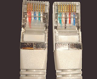
The standard specifies how to connect eight-conductor 100-ohm balanced twisted-pair cabling, such as Category 5 cable, to 8P8C modular connectors (often called RJ45 connectors). The standard defines two alternative pinouts: T568A and T568B.

ANSI/TIA-568 recommends the T568A pinout for horizontal cables. This pinout's advantage is that it is compatible with the 1-pair and 2-pair Universal Service Order Codes (USOC) pinouts. The U.S. Government requires it in federal contracts.[ citation needed ] The standard also allows the T568B pinout, as an alternative, "if necessary to accommodate certain 8-pin cabling systems". This pinout matches the older AT&T 258A (Systimax) pinout. In the 1990s, when the original TIA/EIA-568 was published, T568A had the most widely installed UTP cabling infrastructure. Many organizations still use T568B out of inertia.

The colors of the wire pairs in the cable, in order, are: blue (for pair 1), orange, green, and brown (for pair 4). Each pair consists of one conductor of solid color and a second conductor which is white with a stripe of the other color. The difference between the T568A and T568B pinouts is that the orange and green wire pairs are exchanged.

Wiring

See modular connector for numbering of the pins. [9]

PinT568A pairT568B pair10BASE-T 100BASE-TX [10] 1000BASE-T signal ID [11] WireT568A colorT568B colorPins on plug face
132TX+DA+tip Wire white green stripe.svg
white/green stripe
Wire white orange stripe.svg
white/orange stripe
Rj45plug-8p8c.png
2TX−DA−ring Wire green.svg
green solid
Wire orange.svg
orange solid
323RX+DB+tip Wire white orange stripe.svg
white/orange stripe
Wire white green stripe.svg
white/green stripe
411not usedDC+ring Wire blue.svg
blue solid
Wire blue.svg
blue solid
5not usedDC−tip Wire white blue stripe.svg
white/blue stripe
Wire white blue stripe.svg
white/blue stripe
623RX−DB−ring Wire orange.svg
orange solid
Wire green.svg
green solid
744not usedDD+tip Wire white brown stripe.svg
white/brown stripe
Wire white brown stripe.svg
white/brown stripe
8not usedDD−ring Wire brown.svg
brown solid
Wire brown.svg
brown solid
Some RJ45 wall sockets indicate T568A and T568B termination schemes internally. Commercial RJ45 wall socket internals.jpg
Some RJ45 wall sockets indicate T568A and T568B termination schemes internally.

Note that the only difference between T568A and T568B is that pairs 2 and 3 (orange and green) are swapped. Both configurations wire the pins "straight through", i.e., pins 1 through 8 on one end are connected to pins 1 through 8 on the other end. [12] Also, the same sets of pins connect to the opposite ends that are paired in both configurations: pins 1 and 2 form a pair, as do 3 and 6, 4 and 5, and 7 and 8. One can use cables wired according to either configuration in the same installation without significant problem, as long as the connections are the same on both ends.

Wiring the ends of the same cable according to different configurations (568A on one end and 568B on the other) will create a crossover cable. Crossover cables are occasionally needed for 10Base/T and 100Base/T Ethernet.

Avoid swapping two lines between different pairs. This creates crosstalk. This is rectified by correctly pairing the pins. [13] Crosstalk creates errors in Ethernet, and is more significant with 1GB Ethernet and up, as these standards use all 4 pairs. (10 Base/T and 100 Base/T Ethernet use only 2 pairs, thus swapping two wires in a 4 pair cable has only a 50% chance of affecting 10 Base/T and 100 Base/T Ethernet communications.)

Use for T1 connectivity

In Digital Signal 1 (T1) service, the pairs 1 and 3 (T568A) are used, and the USOC-8 jack is wired as per spec RJ-48C. The Telco termination jack is often wired to spec RJ-48X, which provides for a Transmit-to-Receive loopback when the plug is withdrawn.

Vendor cables are often wired with tip and ring reversed—i.e. pins 1 and 2 reversed, or pins 4 and 5 reversed. This has no effect on the signal quality of the T1 signal, which is fully differential, and uses the Alternate Mark Inversion (AMI) signaling scheme.

Backward compatibility

Because pair 1 connects to the center pins (4 and 5) of the 8P8C connector in both T568A and T568B, both standards are compatible with the first line of RJ11, RJ14, RJ25, and RJ61 connectors that all have the first pair in the center pins of these connectors.

If the second line of an RJ14, RJ25 or RJ61 plug is used, it connects to pair 2 (orange/white) of jacks wired to T568A but to pair 3 (green/white) in jacks wired to T568B. This makes T568B potentially confusing in telephone applications.

Because of different pin pairings, the RJ25 and RJ61 plugs cannot pick up lines 3 or 4 from either T568A or T568B without splitting pairs. This would most likely result in unacceptable levels of hum, crosstalk and noise.

Theory

The original idea in wiring modular connectors, as seen in the registered jacks, was that the first pair would go in the center positions, the next pair on the next outermost ones, and so on. Also, signal shielding would be optimized by alternating the "live" and "earthy" pins of each pair. The terminations diverge slightly from this concept because on the 8 position connector, the resulting pinout would separate the outermost pair impairing balanced line performance too much to meet the electrical requirements of high-speed LAN protocols.

Standards

See also

Related Research Articles

In telecommunications, RS-232, Recommended Standard 232 is a standard originally introduced in 1960 for serial communication transmission of data. It formally defines signals connecting between a DTE such as a computer terminal, and a DCE, such as a modem. The standard defines the electrical characteristics and timing of signals, the meaning of signals, and the physical size and pinout of connectors. The current version of the standard is TIA-232-F Interface Between Data Terminal Equipment and Data Circuit-Terminating Equipment Employing Serial Binary Data Interchange, issued in 1997. The RS-232 standard had been commonly used in computer serial ports and is still widely used in industrial communication devices.

Ethernet over twisted pair Ethernet physical layers using twisted-pair cables

Ethernet over twisted pair technologies use twisted-pair cables for the physical layer of an Ethernet computer network. They are a subset of all Ethernet physical layers.

Category 5 cable

Category 5 cable (Cat 5) is a twisted pair cable for computer networks. Since 2001, the variant commonly in use is the Category 5e specification (Cat 5e). The cable standard provides performance of up to 100 MHz and is suitable for most varieties of Ethernet over twisted pair up to 1000BASE-T. Cat 5 is also used to carry other signals such as telephony and video.

Fast Ethernet Ethernet standards that carry traffic at the nominal rate of 100 Mbit/s

In computer networking, Fast Ethernet physical layers carry traffic at the nominal rate of 100 Mbit/s. The prior Ethernet speed was 10 Mbit/s. Of the Fast Ethernet physical layers, 100BASE-TX is by far the most common.

Category 3 cable, commonly known as Cat 3 or station wire, and less commonly known as VG or voice-grade, is an unshielded twisted pair (UTP) cable used in telephone wiring. It is part of a family of standards defined jointly by the Electronic Industries Alliance (EIA) and the Telecommunications Industry Association (TIA) and published in TIA/EIA-568-B.

StarLAN was the first IEEE 802.3 standard for Ethernet over twisted pair wiring. It was standardized by the standards association of the Institute of Electrical and Electronics Engineers (IEEE) as 802.3e in 1986, as the 1BASE5 version of Ethernet. The StarLAN Task Force was chaired by Bob Galin.

DMX512

DMX512 is a standard for digital communication networks that are commonly used to control stage lighting and effects. It was originally intended as a standardized method for controlling light dimmers, which, prior to DMX512, had employed various incompatible proprietary protocols. It soon became the primary method for linking controllers to dimmers and special effects devices such as fog machines and intelligent lights. DMX has also expanded to uses in non-theatrical interior and architectural lighting, at scales ranging from strings of Christmas lights to electronic billboards and stadium or arena concerts. DMX can now be used to control almost anything, reflecting its popularity in theaters and venues.

Registered jack Telecommunication network interface

A registered jack (RJ) is a standardized telecommunication network interface for connecting voice and data equipment to a service provided by a local exchange carrier or long distance carrier. Registration interfaces were first defined in the Universal Service Ordering Code (USOC) system of the Bell System in the United States for complying with the registration program for customer-supplied telephone equipment mandated by the Federal Communications Commission (FCC) in the 1970s. They were subsequently codified in title 47 of the Code of Federal Regulations Part 68. Registered Jack connections began to see use after their invention in 1973 by Bell Labs. The specification includes physical construction, wiring, and signal semantics. Accordingly, registered jacks are primarily named by the letters RJ, followed by two digits that express the type. Additional letter suffixes indicate minor variations. For example, RJ11, RJ14, and RJ25 are the most commonly used interfaces for telephone connections for one-, two-, and three-line service, respectively. Although these standards are legal definitions in the United States, some interfaces are used worldwide.

RS-422, also known as TIA/EIA-422, is a technical standard originated by the Electronic Industries Alliance that specifies electrical characteristics of a digital signaling circuit. It was intended to replace the older RS-232C standard with a standard that offered much higher speed, better immunity from noise, and longer cable lengths. RS-422 systems can transmit data at rates as high as 10 Mbit/s, or may be sent on cables as long as 1,500 meters at lower rates. It is closely related to RS-423, which used the same signaling systems but on a different wiring arrangement.

A crossover cable connects two devices of the same type, for example DTE-DTE or DCE-DCE, usually connected asymmetrically (DTE-DCE), by a modified cable called a crosslink. Such a distinction between devices was introduced by IBM.

Pinout

In electronics, a pinout is a cross-reference between the contacts, or pins, of an electrical connector or electronic component, and their functions. "Pinout" now supersedes the term "basing diagram" that was the standard terminology used by the manufacturers of vacuum tubes and the RMA. The RMA started its standardization in 1934, collecting and correlating tube data for registration at what was to become the EIA. The EIA now has many sectors reporting to it, and sets what are known as EIA standards where all registered pinouts and registered jacks can be found.

RS-485, also known as TIA-485(-A) or EIA-485, is a standard defining the electrical characteristics of drivers and receivers for use in serial communications systems. Electrical signaling is balanced, and multipoint systems are supported. The standard is jointly published by the Telecommunications Industry Association and Electronic Industries Alliance (TIA/EIA). Digital communications networks implementing the standard can be used effectively over long distances and in electrically noisy environments. Multiple receivers may be connected to such a network in a linear, multidrop bus. These characteristics make RS-485 useful in industrial control systems and similar applications.

Structured cabling

In telecommunications, structured cabling is building or campus cabling infrastructure that consists of a number of standardized smaller elements called subsystems. Structured cabling components include twisted pair and optical cabling, patch panels and patch cables.

Category 6 cable

Category 6 cable (Cat 6), is a standardized twisted pair cable for Ethernet and other network physical layers that is backward compatible with the Category 5/5e and Category 3 cable standards.

EIA-530

Currently known as TIA-530-A, but often called EIA-530, or RS-530, is a balanced serial interface standard that generally uses a 25-pin connector, originally created by the Telecommunications Industry Association.

Ethernet crossover cable

An Ethernet crossover cable is a crossover cable for Ethernet used to connect computing devices together directly. It is most often used to connect two devices of the same type, e.g. two computers or two switches to each other. By contrast, straight through patch cables are used to connect devices of different types, such as a computer to a network switch.

International standard ISO/IEC 11801Information technology — Generic cabling for customer premises specifies general-purpose telecommunication cabling systems that are suitable for a wide range of applications. It covers both balanced copper cabling and optical fibre cabling.

Modular connector Electrical connector commonly used in telephone and computer networks

A modular connector is a type of electrical connector for cords and cables of electronic devices and appliances, such in computer networking, telecommunication equipment, and audio headsets.

In copper twisted pair wire networks, copper cable certification is achieved through a thorough series of tests in accordance with Telecommunications Industry Association (TIA) or International Organization for Standardization (ISO) standards. These tests are done using a certification-testing tool, which provide pass or fail information. While certification can be performed by the owner of the network, certification is primarily done by datacom contractors. It is this certification that allows the contractors to warranty their work.

References

  1. Andrew Oliviero, Bill Woodward "Cabling: The Complete Guide to Copper and Fiber-Optic Networking", John Wiley & Sons, 2009 ISBN   0470550058 page 68
  2. "Standards and Technology Annual Report" (PDF). TIA. Retrieved 2014-04-14.
  3. "TR-42 - Telecommunications Cabling Systems". TIA. Retrieved 2014-04-14.
  4. "TIA-568 Set : Commercial Building Telecommunications Cabling Standards Set".
  5. "TIA Publishes New Cabling Standards Designed to Improve Efficiency for Designers, Installers and End Users". TIA. 2009-03-12. Archived from the original on 2011-08-17.
  6. William Stallings Knowing UTP wiring basics can boost local net performance, Network World 9 July 1996, page 29
  7. Charles E. Spurgeon, Ethernet:The Definitive Guide, (O'Reilly Media, Inc., 2000) ISBN   1565926609 page 212
  8. https://blog.siemon.com/standards/answers-to-your-top-category-8-cabling-questions
  9. "Connector Pin Assignments". Cisco. Retrieved 2014-04-14.
  10. IEEE 802.3 Table 25-2
  11. IEEE 802.3 Table 40-12
  12. "RJ45 Pinout".
  13. "LAN Wiring & Pinouts".

Sources