
An ammeter is an instrument used to measure the current in a circuit. Electric currents are measured in amperes (A), hence the name. For direct measurement, the ammeter is connected in series with the circuit in which the current is to be measured. An ammeter usually has low resistance so that it does not cause a significant voltage drop in the circuit being measured.

An inductor, also called a coil, choke, or reactor, is a passive two-terminal electrical component that stores energy in a magnetic field when electric current flows through it. An inductor typically consists of an insulated wire wound into a coil.
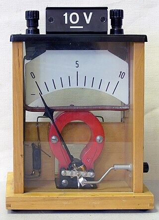
A voltmeter is an instrument used for measuring electric potential difference between two points in an electric circuit. It is connected in parallel. It usually has a high resistance so that it takes negligible current from the circuit.

A Wheatstone bridge is an electrical circuit used to measure an unknown electrical resistance by balancing two legs of a bridge circuit, one leg of which includes the unknown component. The primary benefit of the circuit is its ability to provide extremely accurate measurements. Its operation is similar to the original potentiometer.

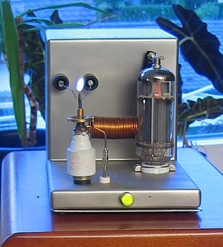
An electrometer is an electrical instrument for measuring electric charge or electrical potential difference. There are many different types, ranging from historical handmade mechanical instruments to high-precision electronic devices. Modern electrometers based on vacuum tube or solid-state technology can be used to make voltage and charge measurements with very low leakage currents, down to 1 femtoampere. A simpler but related instrument, the electroscope, works on similar principles but only indicates the relative magnitudes of voltages or charges.

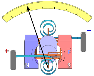
A galvanometer is an electromechanical measuring instrument for electric current. Early galvanometers were uncalibrated, but improved versions, called ammeters, were calibrated and could measure the flow of current more precisely. Galvanometers work by deflecting a pointer in response to an electric current flowing through a coil in a constant magnetic field. The mechanism is also used as an actuator in applications such as hard disks.
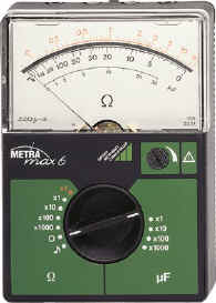
An ohmmeter is an electrical instrument that measures electrical resistance. Multimeters also function as ohmmeters when in resistance-measuring mode. An ohmmeter applies current to the circuit or component whose resistance is to be measured. It then measures the resulting voltage and calculates the resistance using Ohm’s law .
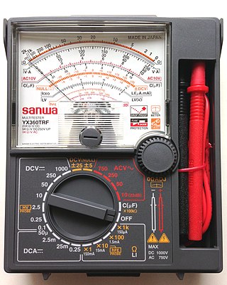
A multimeter is a measuring instrument that can measure multiple electrical properties. A typical multimeter can measure voltage, resistance, and current, in which case can be used as a voltmeter, ohmmeter, and ammeter. Some feature the measurement of additional properties such as temperature and capacitance.

Electromagnetic or magnetic induction is the production of an electromotive force (emf) across an electrical conductor in a changing magnetic field.
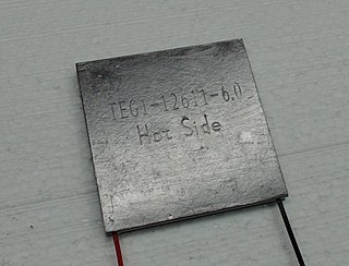
The thermoelectric effect is the direct conversion of temperature differences to electric voltage and vice versa via a thermocouple. A thermoelectric device creates a voltage when there is a different temperature on each side. Conversely, when a voltage is applied to it, heat is transferred from one side to the other, creating a temperature difference.

Jean Charles Athanase Peltier was a French physicist. He was originally a watch dealer, but at the age of 30 began experiments and observations in physics.

A chart recorder is an electromechanical device that records an electrical or mechanical input trend onto a piece of paper. Chart recorders may record several inputs using different color pens and may record onto strip charts or circular charts. Chart recorders may be entirely mechanical with clockwork mechanisms, electro-mechanical with an electrical clockwork mechanism for driving the chart, or entirely electronic with no mechanical components at all.
The following outline is provided as an overview of and topical guide to electrical engineering.

William Du Bois Duddell was an English physicist and electrical engineer. His inventions include the moving coil oscillograph, as well as the thermo-ammeter and thermo-galvanometer.
Plasma speakers or ionophones are a form of loudspeaker which varies air pressure via an electrical plasma instead of a solid diaphragm. The plasma arc heats the surrounding air causing it to expand. Varying the electrical signal that drives the plasma and connected to the output of an audio amplifier, the plasma size varies which in turn varies the expansion of the surrounding air creating sound waves.
Stephen Butterworth (1885–1958) was a British physicist who invented the filter that bears his name, a class of electrical circuits that separates electrical signals of different frequencies.
A potentiometer is an instrument for measuring voltage or 'potential difference' by comparison of an unknown voltage with a known reference voltage. If a sensitive indicating instrument is used, very little current is drawn from the source of the unknown voltage. Since the reference voltage can be produced from an accurately calibrated voltage divider, a potentiometer can provide high precision in measurement. The method was described by Johann Christian Poggendorff around 1841 and became a standard laboratory measuring technique.
In electrical engineering, current sensing is any one of several techniques used to measure electric current. The measurement of current ranges from picoamps to tens of thousands of amperes. The selection of a current sensing method depends on requirements such as magnitude, accuracy, bandwidth, robustness, cost, isolation or size. The current value may be directly displayed by an instrument, or converted to digital form for use by a monitoring or control system.
This glossary of electrical and electronics engineering is a list of definitions of terms and concepts related specifically to electrical engineering and electronics engineering. For terms related to engineering in general, see Glossary of engineering.
