
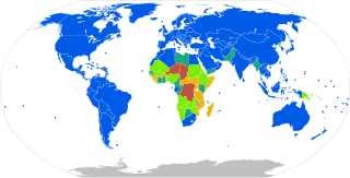
Three-phase electric power is a common type of alternating current used in electricity generation, transmission, and distribution. It is a type of polyphase system employing three wires and is the most common method used by electrical grids worldwide to transfer power.
A schematic, or schematic diagram, is a representation of the elements of a system using abstract, graphic symbols rather than realistic pictures. A schematic usually omits all details that are not relevant to the key information the schematic is intended to convey, and may include oversimplified elements in order to make this essential meaning easier to grasp.
Mains electricity or utility power, power grid, domestic power, and wall power, or in some parts of Canada as hydro, is a general-purpose alternating-current (AC) electric power supply. It is the form of electrical power that is delivered to homes and businesses through the electric grid in many parts of the world. People use this electricity to power everyday items—such as domestic appliances, televisions and lamps—by plugging them into a wall outlet.
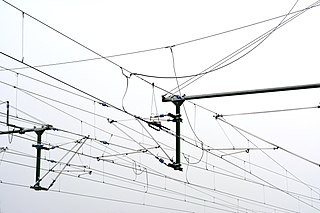
An overhead line or overhead wire is an electrical cable that is used to transmit electrical energy to electric locomotives, trolleybuses or trams. It is known variously as:

A power inverter, inverter or invertor is a power electronic device or circuitry that changes direct current (DC) to alternating current (AC). The resulting AC frequency obtained depends on the particular device employed. Inverters do the opposite of rectifiers which were originally large electromechanical devices converting AC to DC.
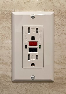
A residual-current device (RCD), residual-current circuit breaker (RCCB) or ground fault circuit interrupter (GFCI) is an electrical safety device that quickly breaks an electrical circuit with leakage current to ground. It is to protect equipment and to reduce the risk of serious harm from an ongoing electric shock. Injury may still occur in some cases, for example if a human receives a brief shock before the electrical circuit is isolated, falls after receiving a shock, or if the person touches both conductors at the same time.
A motor controller is a device or group of devices that can coordinate in a predetermined manner the performance of an electric motor. A motor controller might include a manual or automatic means for starting and stopping the motor, selecting forward or reverse rotation, selecting and regulating the speed, regulating or limiting the torque, and protecting against overloads and electrical faults. Motor controllers may use electromechanical switching, or may use power electronics devices to regulate the speed and direction of a motor.

An arc-fault circuit interrupter (AFCI) or arc-fault detection device (AFDD) is a circuit breaker that breaks the circuit when it detects the electric arcs that are a signature of loose connections in home wiring. Loose connections, which can develop over time, can sometimes become hot enough to ignite house fires. An AFCI selectively distinguishes between a harmless arc, and a potentially dangerous arc.

Two-phase electrical power was an early 20th-century polyphase alternating current electric power distribution system. Two circuits were used, with voltage phases differing by one-quarter of a cycle, 90°. Usually circuits used four wires, two for each phase. Less frequently, three wires were used, with a common wire with a larger-diameter conductor. Some early two-phase generators had two complete rotor and field assemblies, with windings physically offset to provide two-phase power. The generators at Niagara Falls installed in 1895 were the largest generators in the world at that time and were two-phase machines. Three-phase systems eventually replaced the original two-phase power systems for power transmission and utilization. There remain few two-phase distribution systems, with examples in Philadelphia, Pennsylvania; many buildings in Center City are permanently wired for two-phase and Hartford, Connecticut.
Ground and neutral are circuit conductors used in alternating current electrical systems. The ground circuit is connected to earth, and neutral circuit is usually connected to ground. As the neutral point of an electrical supply system is often connected to earth ground, ground and neutral are closely related. Under certain conditions, a conductor used to connect to a system neutral is also used for grounding (earthing) of equipment and structures. Current carried on a grounding conductor can result in objectionable or dangerous voltages appearing on equipment enclosures, so the installation of grounding conductors and neutral conductors is carefully defined in electrical regulations. Where a neutral conductor is used also to connect equipment enclosures to earth, care must be taken that the neutral conductor never rises to a high voltage with respect to local ground.
Electrical wiring in the United Kingdom is commonly understood to be an electrical installation for operation by end users within domestic, commercial, industrial, and other buildings, and also in special installations and locations, such as marinas or caravan parks. It does not normally cover the transmission or distribution of electricity to them.

An overhead power line is a structure used in electric power transmission and distribution to transmit electrical energy across large distances. It consists of one or more uninsulated electrical cables suspended by towers or poles.
An earthing system or grounding system (US) connects specific parts of an electric power system with the ground, typically the Earth's conductive surface, for safety and functional purposes. The choice of earthing system can affect the safety and electromagnetic compatibility of the installation. Regulations for earthing systems vary considerably among countries, though most follow the recommendations of the International Electrotechnical Commission (IEC). Regulations may identify special cases for earthing in mines, in patient care areas, or in hazardous areas of industrial plants.
Impedance is the complex-valued generalization of resistance. It may refer to:
Transposition is the periodic swapping of positions of the conductors of a transmission line, in order to reduce crosstalk and otherwise improve transmission. In telecommunications this applies to balanced pairs whilst in power transmission lines three conductors are periodically transposed.
Power system protection is a branch of electrical power engineering that deals with the protection of electrical power systems from faults through the disconnection of faulted parts from the rest of the electrical network. The objective of a protection scheme is to keep the power system stable by isolating only the components that are under fault, whilst leaving as much of the network as possible in operation. The devices that are used to protect the power systems from faults are called protection devices.
In an electric power system, a fault or fault current is any abnormal electric current. For example, a short circuit is a fault in which a live wire touches a neutral or ground wire. An open-circuit fault occurs if a circuit is interrupted by a failure of a current-carrying wire or a blown fuse or circuit breaker. In three-phase systems, a fault may involve one or more phases and ground, or may occur only between phases. In a "ground fault" or "earth fault", current flows into the earth. The prospective short-circuit current of a predictable fault can be calculated for most situations. In power systems, protective devices can detect fault conditions and operate circuit breakers and other devices to limit the loss of service due to a failure.

A variety of types of electrical transformer are made for different purposes. Despite their design differences, the various types employ the same basic principle as discovered in 1831 by Michael Faraday, and share several key functional parts.

An electric power system is a network of electrical components deployed to supply, transfer, and use electric power. An example of a power system is the electrical grid that provides power to homes and industries within an extended area. The electrical grid can be broadly divided into the generators that supply the power, the transmission system that carries the power from the generating centers to the load centers, and the distribution system that feeds the power to nearby homes and industries.
This glossary of electrical and electronics engineering is a list of definitions of terms and concepts related specifically to electrical engineering and electronics engineering. For terms related to engineering in general, see Glossary of engineering.