
In telecommunications, RS-232 or Recommended Standard 232 is a standard originally introduced in 1960 for serial communication transmission of data. It formally defines signals connecting between a DTE such as a computer terminal or PC, and a DCE, such as a modem. The standard defines the electrical characteristics and timing of signals, the meaning of signals, and the physical size and pinout of connectors. The current version of the standard is TIA-232-F Interface Between Data Terminal Equipment and Data Circuit-Terminating Equipment Employing Serial Binary Data Interchange, issued in 1997.
A data circuit-terminating equipment (DCE) is a device that sits between the data terminal equipment (DTE) and a data transmission circuit. It is also called data communication(s) equipment and data carrier equipment. Usually, the DTE device is the terminal, and the DCE is a modem.
A virtual circuit (VC) is a means of transporting data over a data network, based on packet switching and in which a connection is first established across the network between two endpoints. The network, rather than having a fixed data rate reservation per connection as in circuit switching, takes advantage of the statistical multiplexing on its transmission links, an intrinsic feature of packet switching.

X.25 is an ITU-T standard protocol suite for packet-switched data communication in wide area networks (WAN). It was originally defined by the International Telegraph and Telephone Consultative Committee in a series of drafts and finalized in a publication known as The Orange Book in 1976.

Data terminal equipment (DTE) is an end instrument that converts user information into signals or reconverts received signals. It is also called data processing terminal equipment or tail circuit. A DTE device communicates with the data circuit-terminating equipment (DCE), such as a modem. The DTE/DCE classification was introduced by IBM.

A serial port is a serial communication interface through which information transfers in or out sequentially one bit at a time. This is in contrast to a parallel port, which communicates multiple bits simultaneously in parallel. Throughout most of the history of personal computers, data has been transferred through serial ports to devices such as modems, terminals, various peripherals, and directly between computers.
In the seven-layer OSI model of computer networking, the physical layer or layer 1 is the first and lowest layer: the layer most closely associated with the physical connection between devices. The physical layer provides an electrical, mechanical, and procedural interface to the transmission medium. The shapes and properties of the electrical connectors, the frequencies to transmit on, the line code to use and similar low-level parameters, are specified by the physical layer.

A controller area network (CAN) is a vehicle bus standard designed to enable efficient communication primarily between electronic control units (ECUs). Originally developed to reduce the complexity and cost of electrical wiring in automobiles through multiplexing, the CAN bus protocol has since been adopted in various other contexts. This broadcast-based, message-oriented protocol ensures data integrity and prioritization through a process called arbitration, allowing the highest priority device to continue transmitting if multiple devices attempt to send data simultaneously, while others back off. Its reliability is enhanced by differential signaling, which mitigates electrical noise. Common versions of the CAN protocol include CAN 2.0, CAN FD, and CAN XL which vary in their data rate capabilities and maximum data payload sizes.
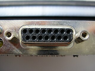
The Attachment Unit Interface (AUI) is a physical and logical interface defined in the IEEE 802.3 standard for 10BASE5 Ethernet and the earlier DIX standard. The physical interface consists of a 15-pin D-subminiature connector that links an Ethernet node's physical signaling to the Medium Attachment Unit (MAU), sometimes referred to as a transceiver. An AUI cable can extend up to 50 metres, though often the MAU and data terminal equipment's (DTE) medium access controller (MAC) are directly connected, bypassing the need for a cable. In Ethernet implementations where the DTE and MAU are combined, the AUI is typically omitted.

RS-422, also known as TIA/EIA-422, is a technical standard originated by the Electronic Industries Alliance, first issued in 1975, that specifies electrical characteristics of a digital signaling circuit. It was meant to be the foundation of a suite of standards that would replace the older RS-232C standard with standards that offered much higher speed, better immunity from noise, and longer cable lengths. RS-422 systems can transmit data at rates as high as 10 Mbit/s, or may be sent on cables as long as 1,200 meters (3,900 ft) at lower rates. It is closely related to RS-423, which uses the same signaling systems but on a different wiring arrangement.
10 Gigabit Attachment Unit Interface is a standard for extending the XGMII between the MAC and PHY layer of 10 Gigabit Ethernet (10GbE) defined in Clause 47 of the IEEE 802.3 standard. The name is a concatenation of the Roman numeral X, meaning ten, and the initials of "Attachment Unit Interface".

A crossover cable connects two devices of the same type, for example DTE-DTE or DCE-DCE, usually connected asymmetrically (DTE-DCE), by a modified cable called a crosslink. Such a distinction between devices was introduced by IBM.
RS-485, also known as TIA-485(-A) or EIA-485, is a standard, originally introduced in 1983, defining the electrical characteristics of drivers and receivers for use in serial communications systems. Electrical signaling is balanced, and multipoint systems are supported. The standard is jointly published by the Telecommunications Industry Association and Electronic Industries Alliance (TIA/EIA). Digital communications networks implementing the standard can be used effectively over long distances and in electrically noisy environments. Multiple receivers may be connected to such a network in a linear, multidrop bus. These characteristics make RS-485 useful in industrial control systems and similar applications.

On-board diagnostics (OBD) is a term referring to a vehicle's self-diagnostic and reporting capability. In the United States, this capability is a requirement to comply with federal emissions standards to detect failures that may increase the vehicle tailpipe emissions to more than 150% of the standard to which it was originally certified.

A serial cable or RS-232 cable is a cable used to transfer information between two devices using a serial communication protocol. The form of connectors depends on the particular serial port used. A cable wired for connecting two DTEs directly is known as a null modem cable.

Currently known as TIA-530-A, but often called EIA-530, or RS-530, is a balanced serial interface standard that generally uses a 25-pin connector, originally created by the Telecommunications Industry Association.

The PS/2 port is a 6-pin mini-DIN connector used for connecting keyboards and mice to a PC compatible computer system. Its name comes from the IBM Personal System/2 series of personal computers, with which it was introduced in 1987. The PS/2 mouse connector generally replaced the older DE-9 RS-232 "serial mouse" connector, while the PS/2 keyboard connector replaced the larger 5-pin/180° DIN connector used in the IBM PC/AT design. The PS/2 keyboard port is electrically and logically identical to the IBM AT keyboard port, differing only in the type of electrical connector used. The PS/2 platform introduced a second port with the same design as the keyboard port for use to connect a mouse; thus the PS/2-style keyboard and mouse interfaces are electrically similar and employ the same communication protocol. However, unlike the otherwise similar Apple Desktop Bus connector used by Apple, a given system's keyboard and mouse port may not be interchangeable since the two devices use different sets of commands and the device drivers generally are hard-coded to communicate with each device at the address of the port that is conventionally assigned to that device.
RS-423, also known as TIA/EIA-423, is a technical standard originated by the Electronic Industries Alliance that specifies electrical characteristics of a digital signaling circuit. Although it was originally intended as a successor to RS-232C offering greater cable lengths, it is not widely used.
Synchronous serial communication describes a serial communication protocol in which "data is sent in a continuous stream at constant rate."
