Axial turbine

Last updated

An axial turbine is a turbine in which the flow of the working fluid is parallel to the shaft, as opposed to radial turbines, where the fluid runs around a shaft, as in a watermill. An axial turbine has a similar construction as an axial compressor, but it operates in the reverse, converting flow of the fluid into rotating mechanical energy.

Contents

A set of static guide vanes or nozzle vanes accelerates and adds swirl to the fluid and directs it to the next row of turbine blades mounted on a turbine rotor.

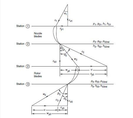
Stage velocity triangle

The angles in the absolute system are noted by alpha (α) and the angles in the relative system are noted by beta (β). Axial and tangential components of both absolute and relative velocities are shown in the figure. Static and stagnation values of pressure and enthalpy in the absolute and relative systems are also shown.

Velocity triangle for a turbine stage Velocity triangle for an axial turbine stage.jpg
Velocity triangle for a turbine stage

It is often assumed that the axial velocity component remains constant through the stage. From this condition we get,
cx = c1 cos α1 = c2 cos α2:= w2 cos β2 = c3 cos α3 = w3 cos α3 Also, for constant axial velocity yields a useful relation:

tan α2 + tan α3 = tan β2 + tan β3

Single impulse stage

A single-stage impulse turbine is shown in Figure

Single-stage impulse turbine Single stage Impulse Turbine.jpg
Single-stage impulse turbine

There is no change in the static pressure through the rotor of an impulse machine. The variation of pressure and velocity of the fluid through the stage is also shown in Figure.

The absolute velocity of the fluid increases corresponding to the pressure drop through the nozzle blade row in which the only transformation of energy occurs. The transfer of energy occurs only across the rotor blade row. Therefore, the absolute fluid velocity decreases through this as shown in the figure. In the absence of any pressure drop through the rotor blades, the relative velocities at their entry and exit are the same for frictionless flow. To obtain this condition the rotor blade angles must be equal. Therefore, the utilization factor is given by

Velocity-compounded impulse turbine

When the pressure drop available is large, it cannot all be used in one turbine stage. A single-stage utilizing a large pressure drop will have an impractically high peripheral speed of its rotor. This would lead to either a larger diameter or a very high rotational speed. Therefore, machines with large pressure drops employ more than one stage.

One of the methods to employ multi-stage expansion in impulse turbines is to generate high-velocity of the fluid by causing it to expand through a large pressure drop in the nozzle blade row. This high-velocity fluid then transfers its energy in a number of stages by employing many rotor blade rows separated by rows of fixed guide blades. A velocity compounded impulse turbine is shown in Figure

One-stage velocity-compounded impulse turbine - Curtis Turbine Two stage velocity compounded impulse turbine.jpg
One-stage velocity-compounded impulse turbine - Curtis Turbine

The decrease in the absolute velocity of the fluid across the two rotor blade rows (R1 and R2) is due to the energy transfer; the slight decrease in the fluid velocity through the fixed guide blades (F) is due to losses. Since the turbine is of the impulse type, the pressure of the fluid remains constant after its expansion in the nozzle blade row. Such stage is referred to as velocity or Curtis stage that each Curtis turbine (nozzle-moving blade-fix blade-moving blade) is counted as one stage.

Multi stage pressure compounded impulse

There are two major problems in velocity-compounded stages:

To avoid these problems, another method of utilizing a ratio is employed in which the total pressure drop is divided into a number of impulse stages. These are known as pressure-compounded or Rateau stages. On account of the comparatively lower pressure drop, the nozzle blade rows are subsonic (M < 1). Therefore, such a stage does not suffer from the disabilities of the velocity stages.

Two-stage pressure-compounded impulse turbine Two stage pressure compounded impulse turbine.jpg
Two-stage pressure-compounded impulse turbine

Figure shows the variation of pressure and velocity of steam through the two pressure stages of an impulse turbine. The nozzle blades in each stage receive flow in the axial direction.

Some designers employ pressure stages up to the last stage. This gives a turbine of shorter length as compared to the reaction type, with a penalty on efficiency.

Reaction stages

Figure shows two reaction stages and the variation of pressure and velocity of the gas in them. The gas pressure decreases continuously over both fixed and moving rows of blades. Since the pressure drop in each stage is smaller as compared to the impulse stages, the gas velocities are relatively low. Besides this the flow is accelerating throughout. These factors make the reaction stages aerodynamically more efficient though the tip leakage loss is increased on account of the relatively higher pressure difference across the rotor blades.

Two-stage reaction turbine Two stage reaction turbine.jpg
Two-stage reaction turbine

Multi-stage reaction turbines employ a large pressure drop by dividing it to smaller values in individual stages. Thus the reaction stages are like the pressure-compounded stages with a new element of “reaction” introduced in them, i.e. of accelerating the flow through rotor blade rows also.

Blade-to-gas speed ratio

Variation of utilization factor and stage efficiency with blade-to-gas speed ratio Variation of utilization factor and stage efficiency with blade-to-gas speed ratio.jpg
Variation of utilization factor and stage efficiency with blade-to-gas speed ratio

The blade-to-gas speed ratio parameter (velocity ratio) σ = u/c2. Efficiencies of the turbine stages can also be plotted against this ratio. Such plots for some impulse and reaction stages are shown in the figure.

The performance of steam turbines is often presented in this form. The curves in Figure also show the optimum values of the velocity ratio and the range of off-design for various types of stages. The fifty per cent reaction stage shows a wider range. Another important aspect that is depicted here is that in applications where high gas velocities (due to high pressure ratio) are unavoidable, it is advisable to employ impulse stages to achieve practical and convenient values of the size and speed of the machine. Sometimes it is more convenient to use an isentropic velocity ratio. This is the ratio of the blade velocity and the isentropic gas velocity that would be obtained in its isentropic expansion through the stage pressure ratio.

Losses and efficiencies

The losses occur in an actual turbine due to disc and bearing friction. Figure shows the energy flow diagram for the impulse stage of an axial turbine. Numbers in brackets indicate the order of energy or loss corresponding to 100 units of isentropic work (h01 – h03ss).

Energy flow diagram for the impulse stage of an axial turbine Energy flow diagram for the impulse stage of an axial turbine.jpg
Energy flow diagram for the impulse stage of an axial turbine

It is seen that the energy reaching the shaft after accounting for stage cascade losses (nozzle and rotor blade aerodynamic losses) and leaving loss is about 85% of the ideal value; shaft losses are a negligible proportion of this value.

See also

Related Research Articles

<span class="mw-page-title-main">Steam turbine</span> Machine that uses steam to rotate a shaft

A steam turbine is a machine that extracts thermal energy from pressurized steam and uses it to do mechanical work on a rotating output shaft. Its modern manifestation was invented by Charles Parsons in 1884. Fabrication of a modern steam turbine involves advanced metalwork to form high-grade steel alloys into precision parts using technologies that first became available in the 20th century; continued advances in durability and efficiency of steam turbines remains central to the energy economics of the 21st century.

<span class="mw-page-title-main">Turbine</span> Rotary mechanical device that extracts energy from a fluid flow

A turbine is a rotary mechanical device that extracts energy from a fluid flow and converts it into useful work. The work produced can be used for generating electrical power when combined with a generator. A turbine is a turbomachine with at least one moving part called a rotor assembly, which is a shaft or drum with blades attached. Moving fluid acts on the blades so that they move and impart rotational energy to the rotor. Early turbine examples are windmills and waterwheels.

<span class="mw-page-title-main">Tesla turbine</span> Bladeless centripetal flow turbine

The Tesla turbine is a bladeless centripetal flow turbine invented by Nikola Tesla in 1913. It functions as nozzles apply a moving fluid to the edges of a set of discs. The engine uses smooth discs rotating in a chamber to generate rotational movement due to the momentum exchange between the fluid and the discs. The discs are arranged in an orientation similar to a stack of CDs on a pole.

<span class="mw-page-title-main">Turbofan</span> Airbreathing jet engine designed to provide thrust by driving a fan

A turbofan or fanjet is a type of airbreathing jet engine that is widely used in aircraft propulsion. The word "turbofan" is a combination of the preceding generation engine technology of the turbojet, and a reference to the additional fan stage added. It consists of a gas turbine engine which achieves mechanical energy from combustion, and a ducted fan that uses the mechanical energy from the gas turbine to force air rearwards. Thus, whereas all the air taken in by a turbojet passes through the combustion chamber and turbines, in a turbofan some of that air bypasses these components. A turbofan thus can be thought of as a turbojet being used to drive a ducted fan, with both of these contributing to the thrust.

<span class="mw-page-title-main">Turbojet</span> Airbreathing jet engine which is typically used in aircraft

The turbojet is an airbreathing jet engine which is typically used in aircraft. It consists of a gas turbine with a propelling nozzle. The gas turbine has an air inlet which includes inlet guide vanes, a compressor, a combustion chamber, and a turbine. The compressed air from the compressor is heated by burning fuel in the combustion chamber and then allowed to expand through the turbine. The turbine exhaust is then expanded in the propelling nozzle where it is accelerated to high speed to provide thrust. Two engineers, Frank Whittle in the United Kingdom and Hans von Ohain in Germany, developed the concept independently into practical engines during the late 1930s.

<span class="mw-page-title-main">Centrifugal compressor</span> Sub-class of dynamic axisymmetric work-absorbing turbomachinery

Centrifugal compressors, sometimes called impeller compressors or radial compressors, are a sub-class of dynamic axisymmetric work-absorbing turbomachinery.

<span class="mw-page-title-main">Compressor</span> Machine to increase pressure of gas by reducing its volume

A compressor is a mechanical device that increases the pressure of a gas by reducing its volume. An air compressor is a specific type of gas compressor.

<span class="mw-page-title-main">Axial compressor</span> Machine for continuous flow gas compression

An axial compressor is a gas compressor that can continuously pressurize gases. It is a rotating, airfoil-based compressor in which the gas or working fluid principally flows parallel to the axis of rotation, or axially. This differs from other rotating compressors such as centrifugal compressor, axi-centrifugal compressors and mixed-flow compressors where the fluid flow will include a "radial component" through the compressor.

<span class="mw-page-title-main">Turbomachinery</span> Machine for exchanging energy with a fluid

Turbomachinery, in mechanical engineering, describes machines that transfer energy between a rotor and a fluid, including both turbines and compressors. While a turbine transfers energy from a fluid to a rotor, a compressor transfers energy from a rotor to a fluid. It is an important application of fluid mechanics.

A compressor map is a chart which shows the performance of a turbomachinery compressor. This type of compressor is used in gas turbine engines, for supercharging reciprocating engines and for industrial processes, where it is known as a dynamic compressor. A map is created from compressor rig test results or predicted by a special computer program. Alternatively the map of a similar compressor can be suitably scaled. This article is an overview of compressor maps and their different applications and also has detailed explanations of maps for a fan and intermediate and high-pressure compressors from a three-shaft aero-engine as specific examples.

A jet engine performs by converting fuel into thrust. How well it performs is an indication of what proportion of its fuel goes to waste. It transfers heat from burning fuel to air passing through the engine. In doing so it produces thrust work when propelling a vehicle but a lot of the fuel is wasted and only appears as heat. Propulsion engineers aim to minimize the degradation of fuel energy into unusable thermal energy. Increased emphasis on performance improvements for commercial airliners came in the 1970s from the rising cost of fuel.

<span class="mw-page-title-main">Gas turbine engine compressors</span> Engine component

As the name suggests, gas turbine engine compressors provide the compression part of the gas turbine engine thermodynamic cycle. There are three basic categories of gas turbine engine compressor: axial compressor, centrifugal compressor and mixed flow compressor. A fourth, unusual, type is the free-piston gas generator, which combines the functions of compressor and combustion chamber in one unit.

<span class="mw-page-title-main">Radial turbine</span> Type of turbine

A radial turbine is a turbine in which the flow of the working fluid is radial to the shaft. The difference between axial and radial turbines consists in the way the fluid flows through the components. Whereas for an axial turbine the rotor is 'impacted' by the fluid flow, for a radial turbine, the flow is smoothly orientated perpendicular to the rotation axis, and it drives the turbine in the same way water drives a watermill. The result is less mechanical stress which enables a radial turbine to be simpler, more robust, and more efficient when compared to axial turbines. When it comes to high power ranges the radial turbine is no longer competitive and the efficiency becomes similar to that of the axial turbines.

<span class="mw-page-title-main">Wind-turbine aerodynamics</span> Physical property

The primary application of wind turbines is to generate energy using the wind. Hence, the aerodynamics is a very important aspect of wind turbines. Like most machines, wind turbines come in many different types, all of them based on different energy extraction concepts.

<span class="mw-page-title-main">Components of jet engines</span> Brief description of components needed for jet engines

This article briefly describes the components and systems found in jet engines.

In turbomachinery, degree of reaction or reaction ratio (R) is defined as the ratio of the static pressure rise in the rotating blades of a compressor (or drop in turbine blades) to the static pressure rise in the compressor stage (or drop in a turbine stage). Alternatively it is the ratio of static enthalpy change in the rotor to the static enthalpy change in the stage.

Compounding of steam turbines is a method of extracting steam energy in multiple stages rather than in a single stage in a steam turbine. A compounded steam turbine has multiple stages with more than one set of nozzles and rotors. These are arranged in series, either keyed to the common shaft or fixed to the casing. The result of this arrangement allows either the steam pressure or the jet velocity to be absorbed by the turbine in a number of stages.

Francis turbine converts energy at high pressure heads which are not easily available and hence a turbine was required to convert the energy at low pressure heads, given that the quantity of water was large enough. It was easy to convert high pressure heads to power easily but difficult to do so for low pressure heads. Therefore, an evolution took place that converted the Francis turbine to Kaplan turbine, which generated power at even low pressure heads efficiently.

Three-dimension losses and correlation in turbomachinery refers to the measurement of flow-fields in three dimensions, where measuring the loss of smoothness of flow, and resulting inefficiencies, becomes difficult, unlike two-dimensional losses where mathematical complexity is substantially less.

Radial means that the fluid is flowing in radial direction that is either from inward to outward or from outward to inward, with respect to the runner shaft axis. If the fluid is flowing from inward to outward then it is called outflow radial turbine.

  1. In this turbine, the working fluid enters around the axis of the wheel and then flows outwards.
  2. The guide vane mechanism is typically surrounded by the runner/turbine.
  3. In this turbine, the inner diameter of the runner is the inlet and outer diameter is an outlet.

References