See also
| | This electronics-related article is a stub. You can help Wikipedia by expanding it. |
A distortion meter is a type of electronic test equipment used to determine specific frequencies that cause distortion in electronic devices. The device is primarily used in audio related equipment.
A typical unit injects a signal in to the input of a circuit and monitors the output of the circuit for distortion.
| | This electronics-related article is a stub. You can help Wikipedia by expanding it. |
An electronic oscillator is an electronic circuit that produces a periodic, oscillating or alternating current (AC) signal, usually a sine wave, square wave or a triangle wave, powered by a direct current (DC) source. Oscillators are found in many electronic devices, such as radio receivers, television sets, radio and television broadcast transmitters, computers, computer peripherals, cellphones, radar, and many other devices.

An amplifier, electronic amplifier or (informally) amp is an electronic device that can increase the magnitude of a signal. It is a two-port electronic circuit that uses electric power from a power supply to increase the amplitude of a signal applied to its input terminals, producing a proportionally greater amplitude signal at its output. The amount of amplification provided by an amplifier is measured by its gain: the ratio of output voltage, current, or power to input. An amplifier is defined as a circuit that has a power gain greater than one.

Electromagnetic compatibility (EMC) is the ability of electrical equipment and systems to function acceptably in their electromagnetic environment, by limiting the unintentional generation, propagation and reception of electromagnetic energy which may cause unwanted effects such as electromagnetic interference (EMI) or even physical damage to operational equipment. The goal of EMC is the correct operation of different equipment in a common electromagnetic environment. It is also the name given to the associated branch of electrical engineering.
A signal generator is one of a class of electronic devices that generates electrical signals with set properties of amplitude, frequency, and wave shape. These generated signals are used as a stimulus for electronic measurements, typically used in designing, testing, troubleshooting, and repairing electronic or electroacoustic devices, though it often has artistic uses as well.

A power inverter, inverter or invertor is a power electronic device or circuitry that changes direct current (DC) to alternating current (AC). The resulting AC frequency obtained depends on the particular device employed. Inverters do the opposite of rectifiers which were originally large electromechanical devices converting AC to DC.

In electronics, a varicap diode, varactor diode, variable capacitance diode, variable reactance diode or tuning diode is a type of diode designed to exploit the voltage-dependent capacitance of a reverse-biased p–n junction.
An RF probe is a device which allows electronic test equipment to measure radio frequency (RF) signal in an electronic circuit.
A low-noise amplifier (LNA) is an electronic component that amplifies a very low-power signal without significantly degrading its signal-to-noise ratio (SNR). Any electronic amplifier will increase the power of both the signal and the noise present at its input, but the amplifier will also introduce some additional noise. LNAs are designed to minimize that additional noise, by choosing special components, operating points, and circuit topologies. Minimizing additional noise must balance with other design goals such as power gain and impedance matching.
This is an index of articles relating to electronics and electricity or natural electricity and things that run on electricity and things that use or conduct electricity.

Audio system measurements are a means of quantifying system performance. These measurements are made for several purposes. Designers take measurements so that they can specify the performance of a piece of equipment. Maintenance engineers make them to ensure equipment is still working to specification, or to ensure that the cumulative defects of an audio path are within limits considered acceptable. Audio system measurements often accommodate psychoacoustic principles to measure the system in a way that relates to human hearing.
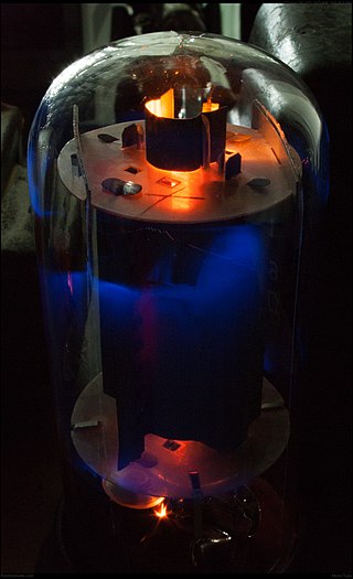
A valve amplifier or tube amplifier is a type of electronic amplifier that uses vacuum tubes to increase the amplitude or power of a signal. Low to medium power valve amplifiers for frequencies below the microwaves were largely replaced by solid state amplifiers in the 1960s and 1970s. Valve amplifiers can be used for applications such as guitar amplifiers, satellite transponders such as DirecTV and GPS, high quality stereo amplifiers, military applications and very high power radio and UHF television transmitters.

Intermodulation (IM) or intermodulation distortion (IMD) is the amplitude modulation of signals containing two or more different frequencies, caused by nonlinearities or time variance in a system. The intermodulation between frequency components will form additional components at frequencies that are not just at harmonic frequencies of either, like harmonic distortion, but also at the sum and difference frequencies of the original frequencies and at sums and differences of multiples of those frequencies.
In electrical engineering and mechanical engineering, the power rating of equipment is the highest power input allowed to flow through particular equipment. According to the particular discipline, the term power may refer to electrical or mechanical power. A power rating can also involve average and maximum power, which may vary depending on the kind of equipment and its application.
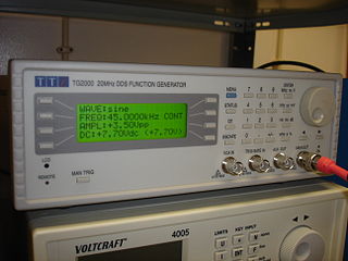
In electrical engineering, a function generator is usually a piece of electronic test equipment or software used to generate different types of electrical waveforms over a wide range of frequencies. Some of the most common waveforms produced by the function generator are the sine wave, square wave, triangular wave and sawtooth shapes. These waveforms can be either repetitive or single-shot. Another feature included on many function generators is the ability to add a DC offset. Integrated circuits used to generate waveforms may also be described as function generator ICs.
In signal processing, when describing a periodic function in the time domain, the DC bias, DC component, DC offset, or DC coefficient is the mean amplitude of the waveform. If the mean amplitude is zero, there is no DC bias. A waveform with no DC bias is known as a DC balanced or DC free waveform.
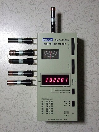
Grid dip oscillator (GDO), also called grid dip meter, gate dip meter, dip meter, or just dipper, is a type of electronic instrument that measures the resonant frequency of nearby unconnected radio frequency tuned circuits. It is a variable-frequency oscillator that circulates a small-amplitude signal through an exposed coil, whose electromagnetic field can interact with adjacent circuitry. The oscillator loses power when its coil is near a circuit that resonates at the same frequency. A meter on the GDO registers the amplitude drop, or "dip", hence the name.

A sweep generator is a piece of electronic test equipment similar to, and sometimes included on, a function generator which creates an electrical waveform with a linearly varying frequency and a constant amplitude. Sweep generators are commonly used to test the frequency response of electronic filter circuits. These circuits are mostly transistor circuits with inductors and capacitors to create linear characteristics.

An audio analyzer is a test and measurement instrument used to objectively quantify the audio performance of electronic and electro-acoustical devices. Audio quality metrics cover a wide variety of parameters, including level, gain, noise, harmonic and intermodulation distortion, frequency response, relative phase of signals, interchannel crosstalk, and more. In addition, many manufacturers have requirements for behavior and connectivity of audio devices that require specific tests and confirmations.
IEC 61000-3-2Electromagnetic compatibility (EMC) – Part 3-2: Limits – Limits for harmonic current emissions is an international standard that limits mains voltage distortion by prescribing the maximum value for harmonic currents from the second harmonic up to and including the 40th harmonic current. IEC 61000-3-2 applies to equipment with a rated current up to 16 A – for equipment above 16 A see IEC 61000-3-12.