In electronics, the figures of merit of an amplifier are numerical measures that characterize its properties and performance. Figures of merit can be given as a list of specifications that include properties such as gain, bandwidth, noise and linearity, among others listed in this article. Figures of merit are important for determining the suitability of a particular amplifier for an intended use.

An amplifier, electronic amplifier or (informally) amp is an electronic device that can increase the power of a signal. It is a two-port electronic circuit that uses electric power from a power supply to increase the amplitude of a signal applied to its input terminals, producing a proportionally greater amplitude signal at its output. The amount of amplification provided by an amplifier is measured by its gain: the ratio of output voltage, current, or power to input. An amplifier is a circuit that has a power gain greater than one.

An operational amplifier is a DC-coupled high-gain electronic voltage amplifier with a differential input and, usually, a single-ended output. In this configuration, an op-amp produces an output potential that is typically hundreds of thousands of times larger than the potential difference between its input terminals. Operational amplifiers had their origins in analog computers, where they were used to perform mathematical operations in many linear, non-linear, and frequency-dependent circuits.

A multimeter or a multitester, also known as a VOM (volt-ohm-milliammeter), is an electronic measuring instrument that combines several measurement functions in one unit. A typical multimeter can measure voltage, current, and resistance. Analog multimeters use a microammeter with a moving pointer to display readings. Digital multimeters have a numeric display, and may also show a graphical bar representing the measured value. Digital multimeters are now far more common due to their lower cost, greater precision having obsoleted analog multimeters.
In telecommunications and professional audio, a balanced line or balanced signal pair is a transmission line consisting of two conductors of the same type, each of which have equal impedances along their lengths and equal impedances to ground and to other circuits. The chief advantage of the balanced line format is good rejection of external noise when fed to a differential amplifier. Common forms of balanced line are twin-lead, used for radio frequency signals and twisted pair, used for lower frequencies. They are to be contrasted to unbalanced lines, such as coaxial cable, which is designed to have its return conductor connected to ground, or circuits whose return conductor actually is ground. Balanced and unbalanced circuits can be interconnected using a transformer called a balun.
Signal-to-noise ratio is a measure used in science and engineering that compares the level of a desired signal to the level of background noise. SNR is defined as the ratio of signal power to the noise power, often expressed in decibels. A ratio higher than 1:1 indicates more signal than noise.
Balanced audio is a method of interconnecting audio equipment using balanced lines. This type of connection is very important in sound recording and production because it allows the use of long cables while reducing susceptibility to external noise caused by electromagnetic interference.

An instrumentationamplifier is a type of differential amplifier that has been outfitted with input buffer amplifiers, which eliminate the need for input impedance matching and thus make the amplifier particularly suitable for use in measurement and test equipment. Additional characteristics include very low DC offset, low drift, low noise, very high open-loop gain, very high common-mode rejection ratio, and very high input impedances. Instrumentation amplifiers are used where great accuracy and stability of the circuit both short and long-term are required.

A differential amplifier is a type of electronic amplifier that amplifies the difference between two input voltages but suppresses any voltage common to the two inputs. It is an analog circuit with two inputs and and one output in which the output is ideally proportional to the difference between the two voltages

A preamplifier is an electronic amplifier that converts a weak electrical signal into an output signal strong enough to be noise-tolerant and strong enough for further processing, or for sending to a power amplifier and a loudspeaker. Without this, the final signal would be noisy or distorted. They are typically used to amplify signals from analog sensors such as microphones and pickups. Because of this, the preamplifier is often placed close to the sensor to reduce the effects of noise and interference.
In an electrical system, a ground loop or earth loop occurs when two points of a circuit which are intended to have the same ground reference potential but instead these two points have a different potential between them. This can be caused, for example, in a signal circuit referenced to ground, if enough current is flowing in the ground to cause two points to be at different potentials.
Analogue electronics are electronic systems with a continuously variable signal, in contrast to digital electronics where signals usually take only two levels. The term "analogue" describes the proportional relationship between a signal and a voltage or current that represents the signal. The word analogue is derived from the Greek word ανάλογος (analogos) meaning "proportional".

In electronics, a choke is an inductor used to block higher-frequency while passing direct current (DC) and lower-frequencies of alternating current (AC) in an electrical circuit. A choke usually consists of a coil of insulated wire often wound on a magnetic core, although some consist of a doughnut-shaped "bead" of ferrite material strung on a wire. The choke's impedance increases with frequency. Its low electrical resistance passes both AC and DC with little power loss, but its reactance limits the amount of AC passed.

In electronics, noise is an unwanted disturbance in an electrical signal. Noise generated by electronic devices varies greatly as it is produced by several different effects.

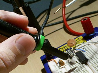
A test probe is a physical device used to connect electronic test equipment to a device under test (DUT). Test probes range from very simple, robust devices to complex probes that are sophisticated, expensive, and fragile. Specific types include test prods, oscilloscope probes and current probes. A test probe is often supplied as a test lead, which includes the probe, cable and terminating connector.
A fully differential amplifier (FDA) is a DC-coupled high-gain electronic voltage amplifier with differential inputs and differential outputs. In its ordinary usage, the output of the FDA is controlled by two feedback paths which, because of the amplifier's high gain, almost completely determine the output voltage for any given input.

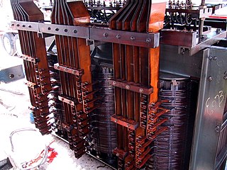
A variety of types of electrical transformer are made for different purposes. Despite their design differences, the various types employ the same basic principle as discovered in 1831 by Michael Faraday, and share several key functional parts.
A balanced circuit is circuitry for use with a balanced line or the balanced line itself. Balanced lines are a common method of transmitting many types of electrical communication signals between two points on two wires. In a balanced line the two signal lines are of a matched impedance to help ensure that interference induced in the line is common-mode and can be removed at the receiving end by circuitry with good common-mode rejection. To maintain the balance, circuit blocks which interface to the line, or are connected in the line, must also be balanced.
A Bioamplifier is an electrophysiological device, a variation of the instrumentation amplifier, used to gather and increase the signal integrity of physiologic electrical activity for output to various sources. It may be an independent unit, or integrated into the electrodes.
Isolation amplifiers are a form of differential amplifier that allow measurement of small signals in the presence of a high common mode voltage by providing electrical isolation and an electrical safety barrier. They protect data acquisition components from common mode voltages, which are potential differences between instrument ground and signal ground. Instruments that are applied in the presence of a common mode voltage without an isolation barrier allow ground currents to circulate, leading in the best case to a noisy representation of the signal under investigation. In the worst case, assuming that the magnitude of common mode voltage or current is sufficient, instrument destruction is likely. Isolation amplifiers are used in medical instruments to ensure isolation of a patient from power supply leakage current.


