This article has multiple issues. Please help to improve it or discuss these issues on the talk page . (Learn how and when to remove these template messages) |
A dry-seal Wiggins gasholder is a device designed to hold gas.
This article has multiple issues. Please help to improve it or discuss these issues on the talk page . (Learn how and when to remove these template messages) |
A dry-seal Wiggins gasholder is a device designed to hold gas.
A dry-seal gasholder can be designed to have a gross (geometric) volume ranging from 200 to 165,000 m3 (7,100 to 5,826,900 cu ft), whilst having a working pressure range between 15 and 150 millibars (1.5 and 15.0 kPa). The dry-seal gasholder is finished with an anti-corrosive treatment to counteract local climatic conditions and also any chemical attack from the stored medium. This anti-corrosive treatment is fully compatible with the sealing membrane and also the environment.[ citation needed ]
The dry seal gasholder has four major elements: the foundation; the main tank; the piston and the sealing membrane. Each of these elements can be divided into various sub-elements and associated accessories.
A concrete and hardcore base designed to withstand the weight of the steel gasholder structure constructed upon it and to withstand dynamic climatic conditions acting upon the gasholder etc.
The main tank is designed to accommodate the design requirements laid down by the customer and climatic conditions. There are three main sub-elements to the tank:
The gasholder piston moves up and down the inside of the shell as gas enters and exits the gasholder. The weight of the piston (less the weight of the level weights) produces the pressure at which the gasholder will operate. The piston is designed to apply an equally distributed weight to ensure that the piston remains level at all times. The piston made up of the following sub-elements:
The seal of the gasholder is designed to operate in the conditions specified by the client and to suit the stored medium. The seal rolls from the shell to the abutment surface of the piston and vice versa providing the piston with a frictionless self-centering facility. During depressurisation the seal (Usually rubber) also provides a gas tight facility that protects the holder from vacuum damage by blocking the gas outlet nozzle. During commissioning of the gasholder the sealing membrane is set into an operating condition. This setting must be carried out every time the gasholder is depressurised, otherwise known as "popping" the seal.[ citation needed ]
A valve is a device or natural object that regulates, directs or controls the flow of a fluid by opening, closing, or partially obstructing various passageways. Valves are technically fittings, but are usually discussed as a separate category. In an open valve, fluid flows in a direction from higher pressure to lower pressure. The word is derived from the Latin valva, the moving part of a door, in turn from volvere, to turn, roll.

A flange is a protruded ridge, lip or rim, either external or internal, that serves to increase strength ; for easy attachment/transfer of contact force with another object ; or for stabilizing and guiding the movements of a machine or its parts. The term "flange" is also used for a kind of tool used to form flanges.

A dry suit or drysuit provides the wearer with environmental protection by way of thermal insulation and exclusion of water, and is worn by divers, boaters, water sports enthusiasts, and others who work or play in or near cold or contaminated water. A dry suit normally protects the whole body except the head, hands, and possibly the feet. In hazmat configurations, however, all of these are covered as well.

A safety valve is a valve that acts as a fail-safe. An example of safety valve is a pressure relief valve (PRV), which automatically releases a substance from a boiler, pressure vessel, or other system, when the pressure or temperature exceeds preset limits. Pilot-operated relief valves are a specialized type of pressure safety valve. A leak tight, lower cost, single emergency use option would be a rupture disk.
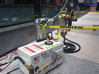
A hydrostatic test is a way in which pressure vessels such as pipelines, plumbing, gas cylinders, boilers and fuel tanks can be tested for strength and leaks. The test involves filling the vessel or pipe system with a liquid, usually water, which may be dyed to aid in visual leak detection, and pressurization of the vessel to the specified test pressure. Pressure tightness can be tested by shutting off the supply valve and observing whether there is a pressure loss. The location of a leak can be visually identified more easily if the water contains a colorant. Strength is usually tested by measuring permanent deformation of the container. Hydrostatic testing is the most common method employed for testing pipes and pressure vessels. Using this test helps maintain safety standards and durability of a vessel over time. Newly manufactured pieces are initially qualified using the hydrostatic test. They are then revalidated at regular intervals according to the relevant standard. In some cases where a hydrostatic test is not practicable a pneumatic pressure test may be an acceptable alternative. Testing of pressure vessels for transport and storage of gases is very important because such containers can explode if they fail under pressure.

A check valve, non-return valve, reflux valve, retention valve, foot valve, or one-way valve is a valve that normally allows fluid to flow through it in only one direction.
A combustion chamber is part of an internal combustion engine in which the fuel/air mix is burned. For steam engines, the term has also been used for an extension of the firebox which is used to allow a more complete combustion process.

A pressure vessel is a container designed to hold gases or liquids at a pressure substantially different from the ambient pressure.
A hydraulic accumulator is a pressure storage reservoir in which an incompressible hydraulic fluid is held under pressure that is applied by an external source of mechanical energy. The external source can be an engine, a spring, a raised weight, or a compressed gas. An accumulator enables a hydraulic system to cope with extremes of demand using a less powerful pump, to respond more quickly to a temporary demand, and to smooth out pulsations. It is a type of energy storage device.

The J-2 was a liquid-fuel cryogenic rocket engine used on NASA's Saturn IB and Saturn V launch vehicles. Built in the U.S. by Rocketdyne, the J-2 burned cryogenic liquid hydrogen (LH2) and liquid oxygen (LOX) propellants, with each engine producing 1,033.1 kN (232,250 lbf) of thrust in vacuum. The engine's preliminary design dates back to recommendations of the 1959 Silverstein Committee. Rocketdyne won approval to develop the J-2 in June 1960 and the first flight, AS-201, occurred on 26 February 1966. The J-2 underwent several minor upgrades over its operational history to improve the engine's performance, with two major upgrade programs, the de Laval nozzle-type J-2S and aerospike-type J-2T, which were cancelled after the conclusion of the Apollo program.

A gas holder or gasholder, also known as a gasometer, is a large container in which natural gas or town gas is stored near atmospheric pressure at ambient temperatures. The volume of the container follows the quantity of stored gas, with pressure coming from the weight of a movable cap. Typical volumes for large gas holders are about 50,000 cubic metres (1,800,000 cu ft), with 60 metres (200 ft) diameter structures.

Hydraulic machines use liquid fluid power to perform work. Heavy construction vehicles are a common example. In this type of machine, hydraulic fluid is pumped to various hydraulic motors and hydraulic cylinders throughout the machine and becomes pressurized according to the resistance present. The fluid is controlled directly or automatically by control valves and distributed through hoses, tubes, or pipes.
A leak is a way for fluid to escape a container or fluid-containing system, such as a tank or a ship's hull, through which the contents of the container can escape or outside matter can enter the container. Leaks are usually unintended and therefore undesired. The word leak usually refers to a gradual loss; a sudden loss is usually called a spill.

A blowout preventer (BOP) is a specialized valve or similar mechanical device, used to seal, control and monitor oil and gas wells to prevent blowouts, the uncontrolled release of crude oil or natural gas from a well. They are usually installed in stacks of other valves.

Oxy-fuel welding and oxy-fuel cutting are processes that use fuel gases and oxygen to weld or cut metals. French engineers Edmond Fouché and Charles Picard became the first to develop oxygen-acetylene welding in 1903. Pure oxygen, instead of air, is used to increase the flame temperature to allow localized melting of the workpiece material in a room environment. A common propane/air flame burns at about 2,250 K, a propane/oxygen flame burns at about 2,526 K, an oxyhydrogen flame burns at 3,073 K and an acetylene/oxygen flame burns at about 3,773 K.
A gas meter prover is a device which verifies the accuracy of a gas meter. Provers are typically used in gas meter repair facilities, municipal gas meter shops, and public works shops. Provers work by passing a known volume of air through a meter while monitoring the gas meters register, index, or internal displacement. The prover then displays a proof, a value expressed as a percent which compares the volume of air passed with the volume of air measured to determine the meters accuracy.

A potato cannon is a pipe-based cannon which uses air pressure (pneumatic), or combustion of a flammable gas, to launch projectiles at high speeds. They are built to fire chunks of potato, as a hobby, or to fire other sorts of projectiles, for practical use. Projectiles or failing guns can be dangerous and result in life-threatening injuries, including cranial fractures, enucleation, and blindness if a person is hit.
Surge control is the use of different techniques and equipment in a hydraulic system to prevent any excessive gain in pressure that would cause the hydraulic process pressure to exceed the maximum working pressure of the mechanical equipment used in the system.
A pipe support or pipe hanger is a designed element that transfer the load from a pipe to the supporting structures. The load includes the weight of the pipe proper, the content that the pipe carries, all the pipe fittings attached to pipe, and the pipe covering such as insulation. The four main functions of a pipe support are to anchor, guide, absorb shock, and support a specified load. Pipe supports used in high or low temperature applications may contain insulation materials. The overall design configuration of a pipe support assembly is dependent on the loading and operating conditions.