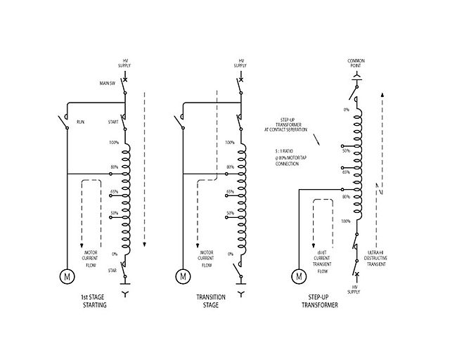
Last updated Korndorfer starter with motor (M), autotransformer (AT) and three switches (1, 2, 3)
In electrical engineering, the Korndorfer starter is a technique used for reduced voltage soft starting of induction motors. The circuit uses a three-phase autotransformer and three three-phase switches. This motor starting method has been updated and improved by Hilton Raymond Bacon.[1]
The Korndorfer starter can be used manually. Newer devices provide full automatic operation, which in addition would have: triple-pole line contactor (switch), start contactor, running contactor, three single-pole overload relays, autotransformer with a set tap-changing links, a suitable timer, and start and stoppushbuttons.[2]
If all switches are open the motor is completely disconnected from the three-phase network.
To start the motor, first the switches 1 and 2 are closed. This supplies the motor a lower voltage from the autotransformer. The lower voltage limits the input current to the initially stationary motor, which accelerates. The torque of the motor is also lowered.
The motor continues to increase its speed until the motor torque and the load torque balance each other and a steady speed is achieved. At this stage switch 2 is opened and momentarily the motor is supplied by even lower voltage, because the windings of the autotransformer act as inductors connected in series with motor. This time is short - just enough to disconnect the switch 1 and engage switch 3, which connects the full voltage to the motor. Further increase in speed begins and motor reaches its full rated speed.
At this point the "soft start" is ended and motor can work under full load. The autotransformer is no longer required and is de-energized by opening switch 1 . The motor is supplied directly from the three-phase network. To stop the motor, switch 3 is opened.
Advantages
The Korndorfer starter limits significantly the inrush current. It is used for large motors, in which start by direct connection to the network is not possible. For large motors also the star-delta starter cannot be used, especially if they are started with a significant load.
The circuit has advantage over starting with a regular autotransformer, which needs to be at some point completely disconnected during the start inducing high voltage impulses, which can damage the electrical insulation of the stator.
The most effective ratio of the autotransformer is between 65-80%.[3]
Drawbacks
The circuit is quite complex and involves relatively expensive autotransformer. Due to the physical size of the whole device it might not be possible to add the Korndorfer starter to an existing machine if space is scarce.
History
The reduced voltage autotransformer starter or Korndorfer starter[4] was invented in 1908, by Max Korndörfer of Berlin. He filed the application with the U.S. Patent office in May 1908 and was granted the patent US 1,096,922 in May 1914. Max Korndörfer assigned his patent to the General Electric Company.
An induction motor draws very high starting current during its acceleration to full rated speed, typically 6 to 10 times the full load current. Reduced starting current is desirable where the electrical grid is not of sufficient capacity, or where the driven load cannot withstand high starting torque. One basic method to reduce the starting current is with a reduced voltage autotransformer with taps at 50%, 65% and 80% of the applied line voltage; once the motor is started the autotransformer is switched out of circuit.
Description of the Korndörfer patent 1,096,922
Max Korndörfer claimed four methods of using an autotransformer for reduced voltage motor starting. Three of the methods are not used by the industry and it is the 4th method of starting that has been in use for more than a hundred years
The fourth method is with the star switch closed and as the motor accelerates a change over is made from the reduced voltage tap on the autotransformer to direct-on-line.
The starting sequence is:-
The Star switch is closed
The Start switch is closed to energise the autotransformer
The motor is connected at a selected reduced voltage tap on the autotransformer and starts to turn and accelerate
After a predetermined period the Star switch will open
After a milli-second delay the Run switch will close, connecting full line voltage to the motor
The Start switch will then open and the motor will be at operational speed
Since 1920, the autotransformer starter has been the most popular device for reducing the starting current inrush for induction motors; it provides maximum starting torque with minimum line current.
Table 1 - Starting Torque /Current with 3 Reduced Voltage taps
Voltage
50%tap
65%tap
80%tap
Torque
25%
42%
64%
Current
50%
65%
80%
Manufactures offer their reduced voltage autotransformer in two configurations, with a 2 coil construction or with a 3 coil construction, figures 2 and 3.
The phase coils are traditional wound in a single coil assembly with the 0 to 50% winding section buried below the 50% to 100% windings in a single thermal mass as shown in figures 2 and 3
Figure 4. 3 Coil Assembly
Figure 4 shows an improved 1000kW 11,000 Volt motor starter autotransformer with
Axial cooling fans,
Cast resin encapsulated coils,
A plurality of windings providing a means of connection as a central switching apparatus,
9 starting voltage tap connections allowing for ± 5% variation of starting torque around NEMA recommended taps at 50%, 65% and 80%. This allows the selection of motor starting torque to be closely matched with the driven load requirements. Selection is by means of the connection links between the winding sections.
Table 2 - Starting Torque /Current with 9 Reduced Voltage Connections
Voltage
45%
50%
55%
60%
65%
70%
75%
80%
85%
Torque
20%
25%
30%
36%
42%
49%
56%
64%
72%
Current
45%
50%
55%
60%
65%
70%
75%
80%
85%
The thermal dissipation of the first starting stage is maximised by being a physically separated winding from the windings of the second starting step to full line voltage.
Uses and styles
The Autotransformer motor starting apparatus is relatively simple compared to solid-state variable frequency drives. Since it does not contain any power electronics devices, the output waveform is a sine wave with no additional harmonic distortion or switching waveforms. No special shielding or cable length limitations are created. Cooling requirements are similar to those of a transformer or switchgear. The reduced-voltage starter provides the maximum torque with a minimum of line current.
Medium voltage starters
The low voltage (<600 V) Korndörfer motor starter is a proven workhorse over the years. However large medium/ high voltage motor starters have reported random autotransformer failures.[5] The IEEE article by Dr.S.E.A. Emam & Pro.Dr.A.H. Amer of the Engineering Consulting Centre at Ain Shams University reports on some investigations made for a petroleum company on a 5,400kW motor, without a clear reason for the failure. In their article they reported that Siemens was called in as a consultant and their solution was to fit R-C suppression /surge arresters similar to that used in other motor starter failures at a Venezuela pumping station.[6] An article in the Wärtsilä technical journal 01.2009, reports that the four 2,900kW thrusters motor autotransformers starters on Q4000 a multipurpose oil drill vessel suffered repeated autotransformer failures prior to 2008. Transformer manufacturers, switchgear manufacture and a European design organization could not give a clear reason for the failures. All auto-transformer six 3000kW starters were replaced by variable speed electronic drives in 2008.[7]
The “open transition” control scheme disconnects the motor from the power source causing the motor to slow down and get out of sync with the power phase, once reconnected, mechanical and electrical transients may damage the motor or its drive train.[8]
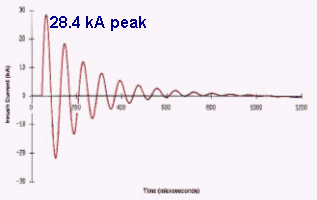
Even with “closed transition” there is a transient produced at contact separation of the Star point switch. The transient is of a very short duration, less than 5 microseconds and occurs when the motor current from the secondary of the autotransformer is forced to the line voltage. This is a very fast event and is the origin of the destructive voltage transients that have caused major breakdowns of large medium and high voltage starters >1000kW.
Figure 5
Michael Faraday D.C.L, F.R.S, in 1831 published a paper on his discovery of electromagnetic induction which is the time rate of change of the magnetic flux with a coil induces a voltage in that coil, the amplitude of the induced voltage is proportional to the velocity of flux linkages with the coil. With normal operation a step-up autotransformer would have flux linkages at the supply frequency; in the case of a very fast dv/dt at the instant of contact separation, the voltage induced into the redundant windings of the first starting stage, will be extremely large. This basic principle explains the source of the destructive transient voltage in the Korndörfer motor starter apparatus.
A further transient problem is that with a single coil construction and a star switch, the autotransformer acts as a step-up transformer during the <5 microsecond period at contact separation of the Star point switch. With the motor connected to the 80% voltage tap there will be an escalation of the transient by 5:1 ratio.
The low voltage Korndörfer autotransformer motor starter <600 volts is also subject to a similar voltage transient with a fast rise wave front, however with a lower operating voltage and state of the art insulation materials in use may be a factor that contributes to its longevity.
To reduce the risk of any voltage surge it is desirable to replace the Korndörfer motor starter circuit with an autotransformer that has a central switch circuit that disconnects redundant windings of the first starting stage from the circuit at the transition, thereby preventing any step-up transformer connection and voltage escalation.
The root cause of destructive transients in Korndörfer starters, it is random switching of the changeover of motor current. The uncontrolled timing of the changeover allows the peak motor current to be switched at any point on the wave. Figure 5 shows the changeover at 90 degrees. This is a worst-case scenario, peak current at changeover, creates a very high and fast transient. The central switch circuit prevents voltage escalation, as discussed above. It is therefore desirable to control the point on the wave at which to switch, the ideal point is when the motor amperes to the lowest value in all the active windings of the autotransformer.
A 3-coil autotransformer requires a 3 pole switch to control 3 phase voltages, an examination of figure 9 shows three sine waves displaced at 120 degree intervals. There appears there is no real point on the cycle where all three phases can be switched simultaneously at any equal low motor amperage without resorting to complex staggered switching methods.
(Left)Figure 9.-3 phase power sine curves (Right)Figure 10. 3-coil Schematic
(Left)Figure11. 2-Coil 2 Phase Sine Curves (Right)Figure 12. 2-Coil Schematic
A 2-coil autotransformer has only two windings that are required to be switched at transition. Figure 11 shows the motor current curves for a 2-coil autotransformer. Line 2 is not switched. This topology is suitable for controlled switching.
An inspection of the sine curves shows that at 30 degrees and 210 degrees, both motor currents are at the same value and are in the same phase quadrant. Therefore the magnetic core flux in first leg of the transformer is the same as the magnetic core flux in the third leg, the centre leg has no windings and its magnetic flux is of no interest. At 30 degrees the amplitude of the motor currents supplied by the autotransformer are only half the peak motor current that occurs at 90 degrees.(sine30° = 0.5) see Figure 8.
The central switch therefore prevents any step-up autotransformer connection and a practicable means of controlling the switching transient to a lower value than the star connected switch.
The important points for controlled central switching are:
The central switch is closed before the motor has power supplied,
There is no break in motor current, only a transfer of current,
A synchronized, controlled opening of the central switch.
Synchronized by means of zero crossing of the motor current waveform.
The central switch may be an electromechanical switch or an electronic device using IGBT, EMT or other similar solid-state devices.
The electronic central switch has only to open its circuit forcing the motor current to transfer into the 80% winding in a no-break, closed transition action. It can provide frictionless, accurate and instant switching actions that are necessary to operate the changeover point at 30 degrees.
A method of detecting current zero crossing is required to provide the timing measurement for controlled switching. A current to voltage transformer is used for accurate triggering of such a timing signal for a controlled switch opening.
Electromechanical central switch has to be carefully selected as it has inherent operating times both opening and closing. It has to have a stored-energy mechanism and a DC operated release solenoid for a controllable “open” command signal. Detection of the motor current zero crossing may be obtained from a current transformer/resistor voltage sensing circuit, not a voltage crossing. The use of electromechanical contactors is not recommended for a central switch as their switch opening speed consistency is subjected to the voltage applied to the hold-in coil. During a motor start the line voltage drop will fluctuate and the magnetic flux in the hold-in device will also vary, causing deviations in opening times.
Controlled switching for reducing motor current surge
The change in motor starting current from the reduced voltage stage can be minimised by switching at transition to a primary reactor second starting stage. In his patent Max Korndörfer shows an external reactor coil method "so as to make the gradation in voltage between steps" before a changeover to direct-on-line.
The external reactor coil method for a second starting stage has merit, as the voltage to the motor is a function of the motor current taken from the line. It can be seen that during a second stage with a series reactor, that during acceleration the motor voltage will rise as the line current drops. This relationship results in greater acceleration energy to a higher motor speed and less disturbance at changeover to full line voltage.
General Electric engineers [9][10] attempted to improve Korndörfer Methods but no methods proposed were successful.
An electromagnetic coil is an electrical conductor such as a wire in the shape of a coil. Electromagnetic coils are used in electrical engineering, in applications where electric currents interact with magnetic fields, in devices such as electric motors, generators, inductors, electromagnets, transformers, and sensor coils. Either an electric current is passed through the wire of the coil to generate a magnetic field, or conversely, an external time-varying magnetic field through the interior of the coil generates an EMF (voltage) in the conductor.
A transformer is a passive component that transfers electrical energy from one electrical circuit to another circuit, or multiple circuits. A varying current in any coil of the transformer produces a varying magnetic flux in the transformer's core, which induces a varying electromotive force (EMF) across any other coils wound around the same core. Electrical energy can be transferred between separate coils without a metallic (conductive) connection between the two circuits. Faraday's law of induction, discovered in 1831, describes the induced voltage effect in any coil due to a changing magnetic flux encircled by the coil.
A Tesla coil is an electrical resonant transformer circuit designed by inventor Nikola Tesla in 1891. It is used to produce high-voltage, low-current, high-frequency alternating-current electricity. Tesla experimented with a number of different configurations consisting of two, or sometimes three, coupled resonant electric circuits.
An electric motor is an electrical machine that converts electrical energy into mechanical energy. Most electric motors operate through the interaction between the motor's magnetic field and electric current in a wire winding to generate force in the form of torque applied on the motor's shaft. An electric generator is mechanically identical to an electric motor, but operates in reverse, converting mechanical energy into electrical energy.
A stepper motor, also known as step motor or stepping motor, is an electrical motor that rotates in a series of small angular steps, instead of continuously. Stepper motors are a type of digital actuator. Like other electromagnetic actuators, they convert electric energy into mechanical energy to perform work.
A power inverter, inverter, or invertor is a power electronic device or circuitry that changes direct current (DC) to alternating current (AC). The resulting AC frequency obtained depends on the particular device employed. Inverters do the opposite of rectifiers which were originally large electromechanical devices converting AC to DC.
An induction motor or asynchronous motor is an AC electric motor in which the electric current in the rotor that produces torque is obtained by electromagnetic induction from the magnetic field of the stator winding. An induction motor therefore needs no electrical connections to the rotor. An induction motor's rotor can be either wound type or squirrel-cage type.
A synchronous electric motor is an AC electric motor in which, at steady state, the rotation of the shaft is synchronized with the frequency of the supply current; the rotation period is exactly equal to an integer number of AC cycles. Synchronous motors use electromagnets as the stator of the motor which create a magnetic field that rotates in time with the oscillations of the current. The rotor with permanent magnets or electromagnets turns in step with the stator field at the same rate and as a result, provides the second synchronized rotating magnet field. A synchronous motor is termed doubly fed if it is supplied with independently excited multiphase AC electromagnets on both the rotor and stator.
A motor controller is a device or group of devices that can coordinate in a predetermined manner the performance of an electric motor. A motor controller might include a manual or automatic means for starting and stopping the motor, selecting forward or reverse rotation, selecting and regulating the speed, regulating or limiting the torque, and protecting against overloads and electrical faults. Motor controllers may use electromechanical switching, or may use power electronics devices to regulate the speed and direction of a motor.
An autotransformer is an electrical transformer with only one winding. The "auto" prefix refers to the single coil acting alone. In an autotransformer, portions of the same winding act as both the primary winding and secondary winding sides of the transformer. In contrast, an ordinary transformer has separate primary and secondary windings that are not connected by an electrically conductive path. between them.
Inrush current, input surge current, or switch-on surge is the maximal instantaneous input current drawn by an electrical device when first turned on. Alternating-current electric motors and transformers may draw several times their normal full-load current when first energized, for a few cycles of the input waveform. Power converters also often have inrush currents much higher than their steady-state currents, due to the charging current of the input capacitance. The selection of over-current-protection devices such as fuses and circuit breakers is made more complicated when high inrush currents must be tolerated. The over-current protection must react quickly to overload or short-circuit faults but must not interrupt the circuit when the inrush current flows.
This is an alphabetical list of articles pertaining specifically to electrical and electronics engineering. For a thematic list, please see List of electrical engineering topics. For a broad overview of engineering, see List of engineering topics. For biographies, see List of engineers.
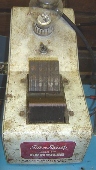
A growler is an electrical device primarily used for testing a motor for shorted coils. A growler consists of a coil of wire wrapped around an iron core and connected to a source of alternating current. When placed on the armature or stator core of a motor the growler acts as the primary of a transformer and the armature coils act as the secondary. A "feeler", a thin strip of steel can be used as the short detector.
An AC motor is an electric motor driven by an alternating current (AC). The AC motor commonly consists of two basic parts, an outside stator having coils supplied with alternating current to produce a rotating magnetic field, and an inside rotor attached to the output shaft producing a second rotating magnetic field. The rotor magnetic field may be produced by permanent magnets, reluctance saliency, or DC or AC electrical windings.
A motor soft starter is a device used with AC electrical motors to temporarily reduce the load and torque in the powertrain and electric current surge of the motor during start-up. This reduces the mechanical stress on the motor and shaft, as well as the electrodynamic stresses on the attached power cables and electrical distribution network, extending the lifespan of the system.
A brushed DC electric motor is an internally commutated electric motor designed to be run from a direct current power source and utilizing an electric brush for contact.
A variety of types of electrical transformer are made for different purposes. Despite their design differences, the various types employ the same basic principle as discovered in 1831 by Michael Faraday, and share several key functional parts.
Amtrak operates a 60 Hz traction power system along the Northeast Corridor between New Haven, Connecticut, and Boston, Massachusetts. This system was built in the late 1990s and supplies locomotives with power from an overhead catenary system at 25 kV alternating current with a frequency of 60 Hz. The system is also commonly known as the Northend Electrification, in contrast to the Southend Electrification that runs between New York City and Washington, D.C.
This glossary of electrical and electronics engineering is a list of definitions of terms and concepts related specifically to electrical engineering and electronics engineering. For terms related to engineering in general, see Glossary of engineering.
Electromagnetically induced acoustic noise (and vibration), electromagnetically excited acoustic noise, or more commonly known as coil whine, is audible sound directly produced by materials vibrating under the excitation of electromagnetic forces. Some examples of this noise include the mains hum, hum of transformers, the whine of some rotating electric machines, or the buzz of fluorescent lamps. The hissing of high voltage transmission lines is due to corona discharge, not magnetism.
↑ Alan L. Sheldrake, Handbook of electrical engineering: for practitioners in the oil, gas and petrochemical industry, John Wiley & Sons, ISBN0-471-49631-6, page 128
↑ USpatent 1096922A,Max Korndörfer,"Method of and apparatus for starting alternating-current motors",published 1908-05-15
↑ The IEEE paper, Farr, L.B.; SmithIII, A.J. (2005). "Medium-Voltage Reduced-Voltage Autotransformer Starter Failures—Explaining the Unexplained". IEEE Transactions on Industry Applications. Institute of Electrical and Electronics Engineers (IEEE). 41 (2): 502–506. doi:10.1109/tia.2005.844396. ISSN0093-9994., identifies the prior art auto-transformer Korndörfer circuit as a producer of fast rise-time voltage surges during a random transition from the first starting stage.
↑ Emam, S.E.A.; Amer, A.H.; Gaber, M. (2008). "Protective measures for transient overvoltages in motors starting by autotransformers". 2008 12th International Middle-East Power System Conference. pp.503–510. doi:10.1109/MEPCON.2008.4562397. ISBN978-1-4244-1933-3. S2CID44728880.
↑ The IEEE paper, Gill, John D. (1979). "Transfer of Motor Loads Between Out-of-Phase Sources". IEEE Transactions on Industry Applications. Institute of Electrical and Electronics Engineers (IEEE). IA-15 (4): 376–381. doi:10.1109/tia.1979.4503676. ISSN0093-9994. S2CID17307995., provides evidence to the danger of using “Open Circuit Transition” in the reduced voltage Autotransformer motor starter apparatus.
This page is based on this Wikipedia article Text is available under the CC BY-SA 4.0 license; additional terms may apply. Images, videos and audio are available under their respective licenses.