A fluid flowing past the surface of a body exerts a force on it. Lift is the component of this force that is perpendicular to the oncoming flow direction. It contrasts with the drag force, which is the component of the force parallel to the flow direction. Lift conventionally acts in an upward direction in order to counter the force of gravity, but it can act in any direction at right angles to the flow.

A wing is a type of fin that produces lift, while moving through air or some other fluid. As such, wings have streamlined cross-sections that are subject to aerodynamic forces and act as an airfoils. A wing's aerodynamic efficiency is expressed as its lift-to-drag ratio. The lift a wing generates at a given speed and angle of attack can be one to two orders of magnitude greater than the total drag on the wing. A high lift-to-drag ratio requires a significantly smaller thrust to propel the wings through the air at sufficient lift.

The delta wing is a wing shaped in the form of a triangle. It is named for its similarity in shape to the Greek uppercase letter delta (Δ).
The center of pressure is the point where the total sum of a pressure field acts on a body, causing a force to act through that point. The total force vector acting at the center of pressure is the value of the integrated vectorial pressure field. The resultant force and center of pressure location produce equivalent force and moment on the body as the original pressure field. Pressure fields occur in both static and dynamic fluid mechanics. Specification of the center of pressure, the reference point from which the center of pressure is referenced, and the associated force vector allows the moment generated about any point to be computed by a translation from the reference point to the desired new point. It is common for the center of pressure to be located on the body, but in fluid flows it is possible for the pressure field to exert a moment on the body of such magnitude that the center of pressure is located outside the body.

Flaps are a kind of high-lift device used to increase the lift of an aircraft wing at a given airspeed. Flaps are usually mounted on the wing trailing edges of a fixed-wing aircraft. Flaps are used for extra lift on takeoff. Flaps also cause an increase in drag in mid-flight, so they are retracted when not needed.
Retreating blade stall is a hazardous flight condition in helicopters and other rotary wing aircraft, where the retreating rotor blade has a lower relative blade speed, combined with an increased angle of attack, causing a stall and loss of lift. Retreating blade stall is the primary limiting factor of a helicopter's never exceed speed, VNE.

A leading-edge slot is a fixed aerodynamic feature of the wing of some aircraft to reduce the stall speed and promote good low-speed handling qualities. A leading-edge slot is a spanwise gap in each wing, allowing air to flow from below the wing to its upper surface. In this manner they allow flight at higher angles of attack and thus reduce the stall speed.

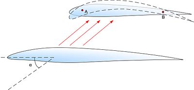
A supercritical airfoil is an airfoil designed primarily to delay the onset of wave drag in the transonic speed range. Supercritical airfoils are characterized by their flattened upper surface, highly cambered ("downward-curved") aft section, and larger leading-edge radius compared with NACA 6-series laminar airfoil shapes. Standard wing shapes are designed to create lower pressure over the top of the wing. The camber of the wing determines how much the air accelerates around the wing. As the speed of the aircraft approaches the speed of sound, the air accelerating around the wing reaches Mach 1 and shockwaves begin to form. The formation of these shockwaves causes wave drag. Supercritical airfoils are designed to minimize this effect by flattening the upper surface of the wing.
Adverse yaw is the natural and undesirable tendency for an aircraft to yaw in the opposite direction of a roll. It is caused by the difference in lift and drag of each wing. The effect can be greatly minimized with ailerons deliberately designed to create drag when deflected upward and/or mechanisms which automatically apply some amount of coordinated rudder. As the major causes of adverse yaw vary with lift, any fixed-ratio mechanism will fail to fully solve the problem across all flight conditions and thus any manually operated aircraft will require some amount of rudder input from the pilot in order to maintain coordinated flight.
Variable camber is a feature of some of aircraft wings that changes the camber of the main aerofoil during flight.
In aeronautics and aeronautical engineering, camber is the asymmetry between the two acting surfaces of an aerofoil, with the top surface of a wing commonly being more convex. An aerofoil that is not cambered is called a symmetric aerofoil. The benefits of cambering were discovered and first utilized by Sir George Cayley in the early 19th century.
Ice protection systems are designed to keep atmospheric ice from accumulating on aircraft surfaces, such as wings, propellers, rotor blades, engine intakes, and environmental control intakes. If ice is allowed to build up to a significant thickness it can change the shape of airfoils and flight control surfaces, degrading the performance, control or handling characteristics of the aircraft. An ice protection system either prevents formation of ice, or enables the aircraft to shed the ice before it can grow to a dangerous thickness.
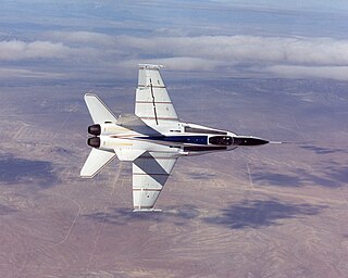
The X-53 Active Aeroelastic Wing (AAW) development program is a completed American research project that was undertaken jointly by the Air Force Research Laboratory (AFRL), Boeing Phantom Works and NASA's Dryden Flight Research Center, where the technology was flight tested on a modified McDonnell Douglas F/A-18 Hornet. Active Aeroelastic Wing Technology is a technology that integrates wing aerodynamics, controls, and structure to harness and control wing aeroelastic twist at high speeds and dynamic pressures. By using multiple leading and trailing edge controls like "aerodynamic tabs", subtle amounts of aeroelastic twist can be controlled to provide large amounts of wing control power, while minimizing maneuver air loads at high wing strain conditions or aerodynamic drag at low wing strain conditions. The flight program which first proved the use of AAW technology in full scale was the X-53 Active Aeroelastic Wing program.

A wingsail is a variable-camber aerodynamic structure that is fitted to a marine vessel in place of conventional sails. Wingsails are analogous to airplane wings, except that they are designed to provide lift on either side to accommodate being on either tack. Whereas wings adjust camber with flaps, wingsails adjust camber with a flexible or jointed structure. Wingsails are typically mounted on an unstayed spar—often made of carbon fiber for lightness and strength. The geometry of wingsails provides more lift, and a better lift-to-drag ratio, than traditional sails. Wingsails are more complex and expensive than conventional sails.

A tailless aircraft has no tail assembly and no other horizontal surface besides its main wing. The aerodynamic control and stabilisation functions in both pitch and roll are incorporated into the main wing. A tailless type may still have a conventional vertical fin and rudder.
The wing configuration of a fixed-wing aircraft is its arrangement of lifting and related surfaces.
In aeronautics, bracing comprises additional structural members which stiffen the functional airframe to give it rigidity and strength under load. Bracing may be applied both internally and externally, and may take the form of strut, which act in compression or tension as the need arises, and/or wires, which act only in tension.