
A bogie is a chassis or framework that carries a wheelset, attached to a vehicle—a modular subassembly of wheels and axles. Bogies take various forms in various modes of transport. A bogie may remain normally attached or be quickly detachable ; it may contain a suspension within it, or be solid and in turn be suspended ; it may be mounted on a swivel, as traditionally on a railway carriage or locomotive, additionally jointed and sprung, or held in place by other means.

A locomotive or engine is a rail transport vehicle that provides the motive power for a train. If a locomotive is capable of carrying a payload, it is usually rather referred to as a multiple unit, motor coach, railcar or power car; the use of these self-propelled vehicles is increasingly common for passenger trains, but rare for freight.

An axle or axletree is a central shaft for a rotating wheel or gear. On wheeled vehicles, the axle may be fixed to the wheels, rotating with them, or fixed to the vehicle, with the wheels rotating around the axle. In the former case, bearings or bushings are provided at the mounting points where the axle is supported. In the latter case, a bearing or bushing sits inside a central hole in the wheel to allow the wheel or gear to rotate around the axle. Sometimes, especially on bicycles, the latter type of axle is referred to as a spindle.

An electric locomotive is a locomotive powered by electricity from overhead lines, a third rail or on-board energy storage such as a battery or a supercapacitor. Locomotives with on-board fuelled prime movers, such as diesel engines or gas turbines, are classed as diesel-electric or gas turbine-electric and not as electric locomotives, because the electric generator/motor combination serves only as a power transmission system.
As used in mechanical engineering, the term tractive force can either refer to the total traction a vehicle exerts on a surface, or the amount of the total traction that is parallel to the direction of motion.
On a steam locomotive, a driving wheel is a powered wheel which is driven by the locomotive's pistons. On a conventional, non-articulated locomotive, the driving wheels are all coupled together with side rods ; normally one pair is directly driven by the main rod which is connected to the end of the piston rod; power is transmitted to the others through the side rods.
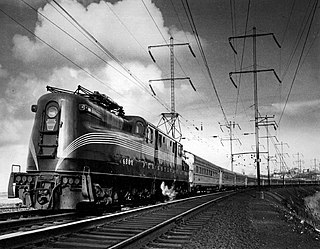
The Pennsylvania Railroad GG1 is a class of streamlined electric locomotives built for the Pennsylvania Railroad (PRR), in the northeastern United States. The class was known for its striking art deco shell, its ability to pull trains at up to 100 mph, and its long operating career of almost 50 years.

A drive shaft, driveshaft, driving shaft, tailshaft, propeller shaft, or Cardan shaft is a component for transmitting mechanical power and torque and rotation, usually used to connect other components of a drivetrain that cannot be connected directly because of distance or the need to allow for relative movement between them.

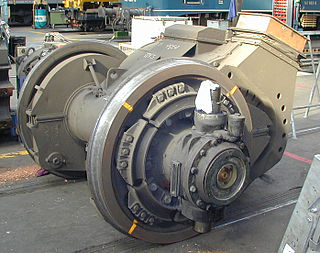
A traction motor is an electric motor used for propulsion of a vehicle, such as locomotives, electric or hydrogen vehicles, or electric multiple unit trains.
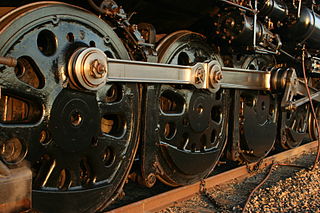
A coupling rod or side rod connects the driving wheels of a locomotive. Steam locomotives in particular usually have them, but some diesel and electric locomotives, especially older ones and shunters, also have them. The coupling rods transfer the power of drive to all wheels.
B-B and Bo-Bo are the Association of American Railroads (AAR) and British classifications of wheel arrangement for railway locomotives with four axles in two individual bogies. They are equivalent to the B′B′ and Bo′Bo′ classifications in the UIC system. The arrangement of two, two-axled, bogies is a common wheel arrangement for modern electric and diesel locomotives.

A jackshaft is an intermediate shaft used to transfer power from a powered shaft such as the output shaft of an engine or motor to driven shafts such as the drive axles of a locomotive. As applied to railroad locomotives in the 19th and 20th centuries, jackshafts were typically in line with the drive axles of locomotives and connected to them by side rods. In general, each drive axle on a locomotive is free to move about one inch (2.5 cm) vertically relative to the frame, with the locomotive weight carried on springs. This means that if the engine, motor or transmission is rigidly attached to the locomotive frame, it cannot be rigidly connected to the axle. This problem can be solved by mounting the jackshaft on unsprung bearings and using side-rods or chain drives.
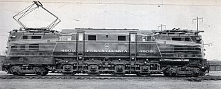
The Pennsylvania Railroad's class R1 comprised a single prototype electric locomotive constructed in 1934 by the Baldwin Locomotive Works of Philadelphia, Pennsylvania, USA, with the electrical equipment by Westinghouse.

The Milwaukee Road's class EP-3 comprised ten electric locomotives built in 1919 by Baldwin and Westinghouse. They were nicknamed Quills because of their use of a quill drive. Although they were good haulers and well liked by engineers, poor design and constant mechanical problems plagued them for their entire lives and they were among the first of the Milwaukee Road's electric locomotives to be retired.

The Buchli drive is a transmission system used in electric locomotives. It was named after its inventor, Swiss engineer Jakob Buchli. The drive is a fully spring-loaded drive, in which each floating axle has an individual motor, that is placed in the spring mounted locomotive frame. The weight of the driving motors is completely disconnected from the driving wheels, which are exposed to movement of the rails.
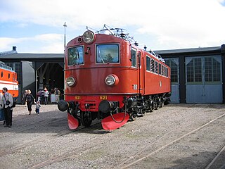
Littera F was a class of electric locomotives operated by the Swedish state railways (SJ) between 1942 and 1983. Twenty-four F-locomotives were constructed and delivered between 1942 and 1949. The design was a rigid-framed locomotive with quill drive and the axle arrangement 1′Do1′, inspired by the German type E 18. The F-locomotives pulled express passenger trains and express freight trains.

A steam motor is a form of steam engine used for light locomotives and light self-propelled motor cars used on railways. The origins of steam motor cars for railways go back to at least the 1850s, if not earlier, as experimental economizations for railways or railroads with marginal budgets. These first examples, at least in North America, appear to have been fitted with light reciprocating engines, and either direct or geared drives, or geared-endless chain drives. Most incorporated a passenger carrying coach attached to the engine and its boiler. Boiler types varied in these earlier examples, with vertical boilers dominant in the first decade and then with very small diameter horizontal boilers. Other examples of steam motor cars incorporated an express-baggage or luggage type car body, with coupling apparatus provided to allow the steam motor car to draw a light passenger coach.

A drivetrain is the group of components that deliver mechanical power from the prime mover to the driven components. In automotive engineering, the drivetrain is the components of a motor vehicle that deliver power to the drive wheels. This excludes the engine or motor that generates the power. In marine applications, the drive shaft will drive a propeller, thruster, or waterjet rather than a drive axle, while the actual engine might be similar to an automotive engine. Other machinery, equipment and vehicles may also use a drivetrain to deliver power from the engine(s) to the driven components.
A cannon bearing or cannon box bearing is an arrangement of bearings on a shaft, usually an axle, where two bearings are mounted in an enclosed tube.

Rigid-framed electric locomotives were some of the first generations of electric locomotive design. When these began the traction motors of these early locomotives, particularly with AC motors, were too large and heavy to be mounted directly to the axles and so were carried on the frame. One of the initial simplest wheel arrangements for a mainline electric locomotive, from around 1900, was the 1′C1′ arrangement, in UIC classification.
