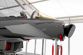
The FPS-16 radar sits atop Tranquillon Peak overlooking all of Vandenberg Air Force Base in California, including Space Launch Complex-6, and the shoreline. Tranquillon Peak's elevation of 2,126 feet (648m) is the highest point on Vandenberg AFB. The radar provides data and range safety for missile launches. This radar, along with its data system, is used for tracking the Minuteman III ICBM.
The AN/FPS-16 is a highly accurate ground-based monopulse single object tracking radar (SOTR), used extensively by the NASA crewed space program, the U.S. Air Force and the U.S. Army. The accuracy of Radar Set AN/FPS-16 is such that the position data obtained from point-source targets has azimuth and elevation angular errors of less than 0.1 milliradian (approximately 0.006 degree) and range errors of less than 5 yards (5m) with a signal-to-noise ratio of 20 decibels or greater.
Under the Joint Electronics Type Designation System (JETDS), all U.S. military radar and tracking systems are assigned a unique identifying alphanumeric designation. The letters “AN” (for Army-Navy) are placed ahead of a three-letter code.[1]
The first letter of the three-letter code denotes the type of platform hosting the electronic device, where A=Aircraft, F=Fixed (land-based), S=Ship-mounted, and T=Ground transportable.
The second letter indicates the type of equipment, where P=Radar (pulsed), Q=Sonar, and R=Radio.
The third letter indicates the function or purpose of the device, where G=Fire control, R=Receiving, S=Search, and T=Transmitting.
Thus, the AN/FPS-16 represents the 16th design of an Army-Navy “Fixed, Radar, Search” electronic device.[1][2]
FPS-16 Monopulse Tracking Radar
The first monopulse radar was developed at the Naval Research Laboratory (NRL) in 1943 to overcome the angular limitations of existing designs. The monopulse technique makes angular determinations simultaneously on each individual received pulse. This improvement in radar technology provides a tenfold increase in angular accuracy over previous fire and missile control radars at longer ranges. The monopulse radar is now the basis for all modern tracking and missile control radars. Although monopulse radar was developed independently and secretly in several countries, Robert Morris Page at the NRL is generally credited with the invention and holds the U.S. patent on this technique.
The monopulse technique was first applied to the Nike-Ajax missile system, an early U.S. continental air defense weapon. Many improvements were made to provide a more compact and efficient monopulse antenna feed and lobe comparison waveguide circuitry, such that monopulse tracking radar became the generally accepted tracking radar system for military and civilian agencies, such as NASA and the FAA.
The NRL's work on monopulse radars eventually led to the AN/FPS-16, developed jointly by NRL and RCA as the first radar designed especially for missile ranges. The AN/FPS-16 was used to guide the first U.S. space satellite launches, Explorer 1 and Vanguard 1, at Cape Canaveral in 1958.
FPS-16 and Project Mercury
The FPS-16 radar at Vandenberg AFB, California has been used for tracking NASA space vehicles since the 1960s.
The C-band monopulse tracking radar (AN/FPS-16) used in the Project Mercury was inherently more accurate than its S-band conically-scanned counterpart, the Very Long Range Tracking (VERLORT) radar system. The AN/FPS-16 radar system was introduced at the Atlantic Missile Test Range with installations including Cape Canaveral, Grand Bahama, San Salvador, Ascension and East Grand Bahama Island between 1958 and 1961. The FPS-16 located on the Australian Weapons Research Establishment Range at Woomera, in South Australia was also linked to the NASA network for Mercury and later missions. NASA Acq aid and telemetry systems were co-located with the Australian radar.
To obtain reliability in providing accurate trajectory data, the Mercury spacecraft was equipped with C-band and S-band cooperative beacons. The ground radar systems had to be compatible with the spacecraft radar beacons. The FPS-16 radar in use at most national missile ranges was selected to meet the C-band requirement. Although it originally had a range capability of only 250 nautical miles (460km), most of the FPS-16 radar units selected for the project had been modified for operation up to 500 nautical miles (900km), a NASA requirement, and modification kits were obtained for the remaining systems. In addition to the basic radar system, it was also necessary to provide the required data-handling equipment to allow data to be transmitted from all sites to the computers.
The FPS-16 system originally planned for the Project Mercury tracking network did not have adequate displays and controls for reliably acquiring the spacecraft in the acquisition time available. Consequently, a contract was negotiated with a manufacturer to provide the instrumentation radar acquisition (IRACQ, Increased RAnge Acquisition) modifications. For the near earth spacecraft involved a major limitation of the FPS-16 was its mechanical range gear box, a wonderful piece of engineering. However, for a target at a range typically, say, 700 nautical miles (1,300km; 810mi) at acquisition of signal [AOS], the radar was tracking second time around, that is, the pulse received in this interpulse period was that due to the previously transmitted pulse, and it would be indicating a range of 700nmi (1,300km; 810mi). As the range closed the return pulse became closer and closer to the time at which the next transmitter pulse should occur. If they were allowed to coincide, remembering that the transmit-receive switch disconnected the receive (Rx) and connected the transmit (Tx) to the antenna at that instant, track would be lost. So, IRACQ provided an electronic ranging system, the function of which was to provide the necessary gating pulses to the Az and El receiver channels so that the system would maintain angle track. The system utilized a voltage controlled crystal oscillator [VCXO] as the clock generator for the range counters. An early/late gate system derived an error voltage which either increased [for a closing target] or decreased [for an opening target] the clock frequency, thus causing the gates to be generated so as to track the target. It also, when the target reached an indicated range of less than 16,000yd (15km), took over the generation of transmitter trigger pulses and delayed these by 16,000yd (15km), thus enabling the received pulses to pass through the Big Bang, as it was called, of normally timed Tx pulses. The radar operator, would, while IRACQ maintained angle track be slewing the range system from minimum range to maximum so as to regain track of the target at its true range of <500 nmi (900km). As the target passed through point of closest approach (PCA) and increased in range the process was repeated at maximum range indication. The most difficult passes were those in which the orbit was such that the target came to PCA at a range of, say 470 nmi. That pass required the radar operator to work very hard as the radar closed, and then opened in range through the Big Bang in short order. The IRACQ Console contained a C-scope associated with which was a small joy stick which gave C-scope operator control of the antenna angle servo systems so that he could adjust the pointing angle to acquire the signal. IRACQ included a scan generator which drove the antenna in one of several pre-determined search patterns around the nominal pointing position, it being desirable that IRACQ acquire the target as early as possible. An essential feature of this modification is that it allows examination of all incoming video signals and allows establishment of angle-only track. Once the spacecraft has been acquired, in angle range. Other features of the IRACQ system included additional angle scan modes and radar phasing controls to permit multiple radar interrogation of the spacecraft beacon. The addition of a beacon local oscillator wave meter permitted the determination of spacecraft-transmitter frequency drift.
Early in the installation program, it was realized that the range of the Bermuda FPS-16 should be increased beyond 500 miles (800km). With the 500-mile (800km)-range limitation, it was possible to track the spacecraft for only 30 seconds prior to launch-vehicle sustainer engine cut-off (SECO) during the critical insertion phase. By extending the range capability to 1,000 miles (2,000km), the spacecraft could be acquired earlier, and additional data could be provided to the Bermuda computer and flight dynamics consort. This modification also increased the probability of having valid data available to make a go/no-go decision after SECO.
The VERLORT radar fulfilled the S-band requirement with only a few modifications. Significant ones were the addition of specific angle-track capability and additional angular scan modes. At Eglin Air Force Base in Florida, the MPQ-31 radar was used for S-band tracking by extending its range capability to meet Project Mercury requirements. The data-handling equipment was essentially the same as for the FPS-16. Coordinate conversion and transmitting equipment was installed at Eglin to allow both the MPQ-31 and the FPS-16 to supply three-coordinate designate data to the Atlantic Missile Range (AMR) radars via central analog data distributing and computing (CADDAC).
C-Band Radar Transponder
The C-Band Radar Transponder (Model SST-135C) is intended to increase the range and accuracy of the radar ground stations equipped with AN/FPS-16, and AN/FPQ-6 Radar Systems. C-band radar stations at the Kennedy Space Center, along the Atlantic Missile Range, and at many other locations around the world, provide global tracking capabilities. Beginning with Vehicles 204 and 501, two C-band radar transponders will be carried in the instrumentation unit (IU) to provide radar tracking capabilities independent of the vehicle attitude. This arrangement is more reliable than the antenna switching circuits necessary if only one transponder would be used.
Transponder operation
The transponder receives coded or single pulse interrogation from ground stations and transmits a single-pulse reply in the same frequency band. A common antenna is used for receiving and transmitting. The transponder consists of five functional systems: superheterodyne receiver, decoder, modulator, transmitter, and power supply. The duplexer (a 4-port ferromagnetic circulator) provides isolation between receiver and transmitter. Interrogating pulses are directed from the antenna to the receiver, and reply pulses are directed from the transmitter to the antenna. The preselector, consisting of three coaxial cavities, attenuates all RF signals outside the receiving band. The received signal is heterodyned to a 50MHz intermediate frequency in the mixer and amplified in the IF amplifier which also contains the detector. In case of coded transmission, the decoder module provides a pulse output only if the correct spacing exists between pulse pairs received. The shaped-pulse output of the decoder is directed to the modulator which converts it into a high-power, precisely shaped and precisely delayed pulse which is applied to the magnetron to produce the reply pulse. Six telemetry outputs are provided: input signal level, input pulse repetition frequency (PRF), temperature, incident power, reflected power, and reply PRF.
Semiconductors are used in all circuitry, with the exception of the local oscillator and magnetron.
Radar ground station operation
The radar ground stations determine the position of the vehicle C-band transponder by measuring range, azimuth angle, and elevation angle. Range is derived from pulse travel time, and angle tracking is accomplished by amplitude-comparison monopulse techniques. As many as four radar stations may track the beacon simultaneously.
NASA Manned Space Flight Network (MSFN) C-band Radar
The NASA Manned Space Flight Network (MSFN) land based C-band pulse radar types consist of the AN/FPS-16, AN/MPS-39, AN/FPQ-6 and the AN/TPQ-18. The MPS-39 is a transportable instrument using space-fed-phased-array technology; the TPQ-18, a transportable version of the FPQ-6. The indicator AN (originally "Army–Navy") does not necessarily mean that the Army, Navy or Air Force use the equipment, but simply that the type nomenclature was assigned according to the military nomenclature system. The meaning of the three letter prefixes; FPS, MPS, FPQ and TPQ are:
FPS - fixed; radar; detecting and/or range and bearing
MPS - ground, mobile; radar; detecting and/or range and bearing
FPQ - fixed; radar; special, or combination of purposes
TPQ - ground, transportable; radar; special, or combination of purposes.
AN/FPS-16 RADAR SET TYPICAL TECHNICAL SPECIFICATIONS ------------------------ Type of presentation: Dual-trace CRT, A/R and R type displays. Transmitter data - Nominal Power: 1 MW peak (fixed-frequency magnetron); 250 kW peak (tunable magnetron). Frequency Fixed: 5480 plus or minus 30 MHz Tunable: 5450 to 5825 MHz Pulse repetition frequency (internal): 341, 366, 394, 467, 569, 682, 732, 853, 1024, 1280, 1364 or 1707 pulses per second Pulse width: 0.25, 0.50, 1.0 μs Code groups: 5 pulses max, within 0.001 duty cycle limitation of transmitter. Radar receiver data - Noise Figure: 11 dB Intermediate Frequency: 30 MHz Bandwidth: 8 MHz Narrow Bandwidth: 2 MHz Dynamic Range of Gain Control: 93 dB Gate width Tracking: 0.5 μs, 0.75 μs, 1.25 μs Acquisition: 1.0 μs, 1.25 μs, 1.75 μs Coverage Range: 500 to {{convert|400000|yd|m|-5|abbr=on}} Azimuth: 360° continuous Elevation: minus 10 to plus 190 degrees Servo bandwidth Range: 1 to 10 Hz (var) Angle: 0.25 to 5 Hz (var) Operating power requirements: 115 V AC, 60 Hz, 50 kV·A, 3 phase
Principles of operation
AN/FPS-16 Radar Set block diagram.
The AN/FPS-16 is a C-band monopulse radar utilizing a waveguide hybrid-labyrinth comparator to develop angle track information. The comparator receives RF signals from an array of four feed horns which are located at the focal point of a 12-foot (4m) parabolic reflector. The comparator performs vector addition and subtraction of the energy received by each horn. The elevation tracking data is generated in the comparator as the difference between the sums of the top two horns. The azimuth tracking error is the difference between the sums of the two vertical horn pairs. The vectorial sums of all four horns is combined in a third channel. Three mixers with a common local oscillator, and three 30MHz IF strips are used; one each for the azimuth, elevation, and sum signals.
The same four-horn cluster is used for RF transmission. The transmitter output is delivered to the comparator labyrinth, which now acts to divide the outgoing power equally between all four horns. The receivers are protected by TR tubes during the transmit time.
The horn cluster is located approximately at the focal point of a 12-foot (4m)parabolic reflector. During the transmission cycle, the energy is distributed equally among the four horns. During the receive cycle, the outputs of the elevation and azimuth comparator arms represent the amount of angular displacement between the target position and electrical axis. Consider an off-axis target - the image is displaced from the focal point, and the difference in signal intensity at the face of the horns is indicative of angular displacement. An on-target condition will cause equal and in-phase signals at each of the four horns and zero output from the elevation and azimuth arms.
The sum, azimuth, and elevation signals are converted to 30 MHzIF signals and amplified. The phases of the elevation and azimuth signals are then compared with the sum signal to determine error polarity. These errors are detected, commutated, amplified, and used to control the antenna-positioning servos. A part of the reference signal is detected and used as a video range tracking signal and as the video scope display. A highly precise antenna mount is required to maintain the accuracy of the angle system.
The FPS-16 antenna pedestal is a precision-machined item, engineered to close tolerances, assembled in dust-free, air-conditioned rooms to prevent warping during mechanical assembly. The pedestal is mounted on a reinforced concrete tower to provide mechanical rigidity. The electronic equipment is mounted in a two-story concrete building, which surrounds the tower to decrease tower warping due to solar radiation.
The radar utilizes a 12-foot (4m)parabolic antenna giving a beamwidth of 1.2 degrees at the half-power points. The range system uses 1.0, 0.5, or 0.25-microsecond wide pulses. Pulse width and prf can be set by pushbuttons. Twelve repetition frequencies between 341 and 1707 pulses per second can be selected. A jack is provided through which the modulator can be pulsed by an external source. By means of external modulation, a code of 1 to 5 pulses may be used.
Data rake-offs are provided for potentiometer, synchro, and digital information in all three coordinates. The azimuth and elevation digital data is derived from optical-type analog-to-digital encoders. Two geared coders with ambiguity resolution are used for each parameter. The data for each angle is a Gray code 17-bit word in serial form. The overlapping ambiguity bits are removed, and the data is transformed from cyclic Gray code to straight binary before recording for transmission to the computer. The range servo presents a 20-bit straight binary word in serial form after ambiguity resolution and code conversion. The same type optical encoders are used.
The AN/FPS-16 antenna pedestal is mounted on a 12-by-12-foot (4 by 4m) concrete tower which extends 27 feet (8m) above grade level. The center of the emplaced antenna is approximately 36 feet (11m) above grade level. The electronic equipment, auxiliary system, maintenance section, etc., are housed in a 66 by 30 by 24ft (20×9×7 m) two-story concrete block building. The building surrounds, but is not attached to, the pedestal tower. This method of construction places the tower within the air conditioned environment of the equipment building and provides protection from solar radiation and other weather effects which would dilute the inherent accuracy of the system. Power requirements for each station are: 120/208 volts, ±10 volts, 4-wire, 60Hz; 175 kV·A.
Models of the AN/FPS-16
The AN/FPS-16 and AN/FPQ-6 are C-band tracking radar systems. Their key characteristics are compared in the following table.
Radar Ground Station Characteristics ------------------------------------ AN/FPS-16 AN/FPQ-6 --------- --------- Frequency band (MHz) . . 5400-5900 5400-5900 Peak power (MW) ...... 1.3 3.0 Antenna size (meters) .... 3.9 9.2 Antenna gain (dB) ...... 47 52 Receiver noise figure (dB) 6.5 8 Angle precision (units) . . . 0.15 0.1 Range precision (meters).. 4.5 3.0
AN/FPS-16 (XN-I)
The first experimental model was made with an X-band RF system and a lens-type antenna. It later was changed to C-band with a reflector antenna. This radar was further modified for use on Vanguard and is now installed at the Atlantic Missile Range, Patrick AFB, Florida.
AN/FPS-16 (XN-
Two of this model were made. One was installed on Grand Bahama Island, BWI, and one remained at RCA (now Lockheed Martin), Moorestown, N.J. These radars are almost identical to later production models.
AN/FPS-16 (XN-3)
This was an experimental version of AN/FPS-16 (XN-2) that includes a 3-megawatt modification kit, a circular polarization kit, a data correction kit, and a boresight television kit. This radar was installed at RCA, Moorestown, N.J.
AN/FPS-16AX
This is a production AN/FPS-16 modified according to (XN-3). Three radars located at White Sands Missile Range, and one located at Moorestown, New Jersey, have been so modified. AN/MPS-25 is the nomenclature of a trailer-mounted production model AN/FPS-16.
AN/FPQ-4
This is an adaptation of AN/FPS-16 that was made for use as a target tracker in the land-based Talos system. Two models were installed at WSMR. Two more models, with modifications, were installed on a ship for use in the Atlantic Missile Range on the Project DAMP. A fifth such radar was installed at RCA, Moorestown, N.J. as a part of the Project DAMP research facility.
AN/FPS-16 RADAR SET PRINCIPAL COMPONENTS AND PHYSICAL DATA -------------------------------------- COMPONENTS QTY OVERALL DIMENSIONS UNIT WT. (Inches) (Pounds) ---------- --- ------------------ -------- Amplifier Electronic Control 1 3.1 x 3.7 x 10.4 6 AM-1751/FPS-16 Tuning Drive 1 3.1 x 3.i x 10 3 TG-55/FPS-16 Control Electrical Frequency 1 3.7 x 4.7 x 19.2 6 C-2278/FPS-16 Control Amplifier 1 3.7 x 1.7 x 17.2 5 C-2276/FPS-16 Air Conditioner 1 32 x 56 x 73 1500 Air Conditioner 1 18 x 72 x 76 1500 Amplifier Filament Supply 13 3.7 x 3.7 x 5 1 Angle Compensation Amplifier 2 8.2 x 15.5 x 19.5 24 (Azimuth & Elevation) Angle Control Unit 1 8.2 x 15.5 x 19.5 20 AM-1760/FPS-16 Angle Error Amplifier 2 8.2 x 13.7 x 19.5 21 (Azimuth & Elevation) Angle Servo Preamplifier 2 2.5 x 6 x 19.5 10 (Azimuth Servo; Elevation Servo) Angle Summing Amplifier 2 12.2 x 15.5 x 19.5 24 (Azimuth & Elevation) Azimuth Driver Amplifier 1 8.2 x 13.7 x 19.5 21 AM-1759/FPS-16
Upgrade Modifications
Significant improvements and updates were incorporated in numerous AN/FPS-16 & TPQ-18 systems through and beyond the 1960s.
Digital Ranging Machine (DIRAM, ADRAN) The electro-mechanical range servo tracking machine was replaced with a hard-wired digital logic Range tracking subsystem (a couple of generations). Analog receiver inputs of Early-Late gate range error signals integrated to produce count-up/down increments to the Range Counter which was decoded to produce tracking gates and display triggers to about ~5.25MHz (~190nSec) resolution. Similar counting and decoding was used to generate transmit timing (T0, PRF, ...). Some higher resolution timing was generated with a tapped delay-line technique.
Doppler Velocity Extraction System (DVES) This modification included the Digital Ranging modification, and added a general purpose digital computer, and a sub-set of the AN/FPQ-6 CSP (coherent signal processor) Doppler Velocity tracking sub-system (see AN/FPQ-6). The FPS-16 (and MPS-36) omitted CSP function was the received signal I&Q IF integration in very narrow crystal filters. The coherent transmit and LO receive and Doppler Velocity tracking servo loops were included for clean un-ambiguous velocity data. The general purpose digital computer provided the Pulse Doppler ambiguity resolution filtering, implemented the angle servo loop-closure for Az-El tracking, and other functions.
Related Research Articles
Radar is a system that uses radio waves to determine the distance (ranging), direction, and radial velocity of objects relative to the site. It is a radiodetermination method used to detect and track aircraft, ships, spacecraft, guided missiles, motor vehicles, map weather formations, and terrain.
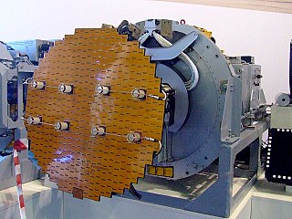
In antenna theory, a phased array usually means an electronically scanned array, a computer-controlled array of antennas which creates a beam of radio waves that can be electronically steered to point in different directions without moving the antennas. The general theory of an electromagnetic phased array also finds applications in ultrasonic and medical imaging application and in optics optical phased array.
A Doppler radar is a specialized radar that uses the Doppler effect to produce velocity data about objects at a distance. It does this by bouncing a microwave signal off a desired target and analyzing how the object's motion has altered the frequency of the returned signal. This variation gives direct and highly accurate measurements of the radial component of a target's velocity relative to the radar. The term applies to radar systems in many domains like aviation, police radar detectors, navigation, meteorology, etc.
MISTRAM was a high-resolution tracking system used by the United States Air Force to provide highly detailed trajectory analysis of rocket launches.
Synthetic-aperture radar (SAR) is a form of radar that is used to create two-dimensional images or three-dimensional reconstructions of objects, such as landscapes. SAR uses the motion of the radar antenna over a target region to provide finer spatial resolution than conventional stationary beam-scanning radars. SAR is typically mounted on a moving platform, such as an aircraft or spacecraft, and has its origins in an advanced form of side looking airborne radar (SLAR). The distance the SAR device travels over a target during the period when the target scene is illuminated creates the large synthetic antenna aperture. Typically, the larger the aperture, the higher the image resolution will be, regardless of whether the aperture is physical or synthetic – this allows SAR to create high-resolution images with comparatively small physical antennas. For a fixed antenna size and orientation, objects which are further away remain illuminated longer – therefore SAR has the property of creating larger synthetic apertures for more distant objects, which results in a consistent spatial resolution over a range of viewing distances.
An active electronically scanned array (AESA) is a type of phased array antenna, which is a computer-controlled antenna array in which the beam of radio waves can be electronically steered to point in different directions without moving the antenna. In the AESA, each antenna element is connected to a small solid-state transmit/receive module (TRM) under the control of a computer, which performs the functions of a transmitter and/or receiver for the antenna. This contrasts with a passive electronically scanned array (PESA), in which all the antenna elements are connected to a single transmitter and/or receiver through phase shifters under the control of the computer. AESA's main use is in radar, and these are known as active phased array radar (APAR).
Imaging radar is an application of radar which is used to create two-dimensional images, typically of landscapes. Imaging radar provides its light to illuminate an area on the ground and take a picture at radio wavelengths. It uses an antenna and digital computer storage to record its images. In a radar image, one can see only the energy that was reflected back towards the radar antenna. The radar moves along a flight path and the area illuminated by the radar, or footprint, is moved along the surface in a swath, building the image as it does so.
The history of radar started with experiments by Heinrich Hertz in the late 19th century that showed that radio waves were reflected by metallic objects. This possibility was suggested in James Clerk Maxwell's seminal work on electromagnetism. However, it was not until the early 20th century that systems able to use these principles were becoming widely available, and it was German inventor Christian Hülsmeyer who first used them to build a simple ship detection device intended to help avoid collisions in fog. True radar, such as the British Chain Home early warning system provided directional information to objects over short ranges, were developed over the next two decades.
A pulse-Doppler radar is a radar system that determines the range to a target using pulse-timing techniques, and uses the Doppler effect of the returned signal to determine the target object's velocity. It combines the features of pulse radars and continuous-wave radars, which were formerly separate due to the complexity of the electronics.
Secondary surveillance radar (SSR) is a radar system used in air traffic control (ATC), that unlike primary radar systems that measure the bearing and distance of targets using the detected reflections of radio signals, relies on targets equipped with a radar transponder, that reply to each interrogation signal by transmitting encoded data such as an identity code, the aircraft's altitude and further information depending on its chosen mode. SSR is based on the military identification friend or foe (IFF) technology originally developed during World War II; therefore, the two systems are still compatible. Monopulse secondary surveillance radar (MSSR), Mode S, TCAS and ADS-B are similar modern methods of secondary surveillance.
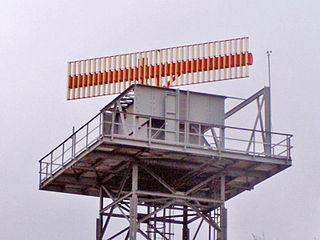
The air traffic control radar beacon system (ATCRBS) is a system used in air traffic control (ATC) to enhance surveillance radar monitoring and separation of air traffic. It consists of a rotating ground antenna and transponders in aircraft. The ground antenna sweeps a narrow vertical beam of microwaves around the airspace. When the beam strikes an aircraft, the transponder transmits a return signal back giving information such as altitude and the Squawk Code, a four digit code assigned to each aircraft that enters a region. Information about this aircraft is then entered into the system and subsequently added to the controller's screen to display this information when queried. This information can include flight number designation and altitude of the aircraft. ATCRBS assists air traffic control (ATC) surveillance radars by acquiring information about the aircraft being monitored, and providing this information to the radar controllers. The controllers can use the information to identify radar returns from aircraft and to distinguish those returns from ground clutter.
Monopulse radar is a radar system that uses additional encoding of the radio signal to provide accurate directional information. The name refers to its ability to extract range and direction from a single signal pulse.
An airport surveillance radar (ASR) is a radar system used at airports to detect and display the presence and position of aircraft in the terminal area, the airspace around airports. It is the main air traffic control system for the airspace around airports. At large airports it typically controls traffic within a radius of 60 miles (96 km) of the airport below an elevation of 25,000 feet. The sophisticated systems at large airports consist of two different radar systems, the primary and secondary surveillance radar. The primary radar typically consists of a large rotating parabolic antenna dish that sweeps a vertical fan-shaped beam of microwaves around the airspace surrounding the airport. It detects the position and range of aircraft by microwaves reflected back to the antenna from the aircraft's surface. The secondary surveillance radar consists of a second rotating antenna, often mounted on the primary antenna, which interrogates the transponders of aircraft, which transmits a radio signal back containing the aircraft's identification, barometric altitude, and an emergency status code, which is displayed on the radar screen next to the return from the primary radar.
The Downrange Anti-missile Measurement Program or DAMP was an applied research project to obtain scientific data, just prior to and during re-entry, on intermediate- and intercontinental-range ballistic missiles as they returned to earth. The program was funded by the Advanced Research Projects Agency (ARPA) under the technical direction of the Army Ordnance Missile Command (AOMC) during the period 1 January 1959 through 30 September 1963.
A radar system uses a radio-frequency electromagnetic signal reflected from a target to determine information about that target. In any radar system, the signal transmitted and received will exhibit many of the characteristics described below.
The AN/FPS-17 was a ground-based fixed-beam radar system that was installed at three locations worldwide, including Pirinçlik Air Base in south-eastern Turkey, Laredo, Texas and Shemya Island, Alaska.
The AN/FPQ-6 is a fixed, land-based C-band radar system used for long-range, small-target tracking. The AN/FPQ-6 Instrumentation Radar located at the NASA Kennedy Space Center was the principal C-Band tracking radar system for Apollo program.
Radar engineering is the design of technical aspects pertaining to the components of a radar and their ability to detect the return energy from moving scatterers — determining an object's position or obstruction in the environment. This includes field of view in terms of solid angle and maximum unambiguous range and velocity, as well as angular, range and velocity resolution. Radar sensors are classified by application, architecture, radar mode, platform, and propagation window.
Moving target indication (MTI) is a mode of operation of a radar to discriminate a target against the clutter. It describes a variety of techniques used for finding moving objects, like an aircraft, and filter out unmoving ones, like hills or trees. It contrasts with the modern stationary target indication (STI) technique, which uses details of the signal to directly determine the mechanical properties of the reflecting objects and thereby find targets whether they are moving or not.
The AN/FPS-6 Radar was a long-range height finding radar used by the United States Air Force's Air Defense Command. The AN/FPS-6 radar was introduced into service in the late 1950s and served as the principal height-finder radar for the United States for several decades thereafter. It was also used by the Royal Air Force alongside their AMES Type 80s. Built by General Electric, the S-band radar operated on a frequency of 2700 to 2900 MHz. Between 1953 and 1960, about 450 units of the AN/FPS-6 and the mobile AN/MPS-14 version were produced. The AN/FPS-90 and AN/FPS-116 radars were identical to the AN/FPS-6 except for receiver modifications.
Radar Set - Type: AN/FPS-16. US Air Force TM-11-487C-1, Volume 1, MIL-HDBK-162A. 15 December 1965.
R.M. Page. Accurate angle tracking by radar. NRL Report RA-3A-222A, December 28, 1944.
U.S. Patent No. 2,929,056 to R.M. Page, "Simultaneous Lobing Tracking Radar", March 1960.
L.A. Gebhard. Evolution of Naval Radio-Electronics and Contributions of the Naval Research Laboratory. NRL Report 8300, 1979.
NASA Publication SP-45, "Mercury Project Summary, Including Results of the Fourth Manned Orbital Flight, May 15 and 16, 1963. October 1963.
Danielsen, E. F.; Duquet, R. T. A Comparison of FPS-16 and GMD-1 Measurements and Methods for Processing Wind Data. Journal of Applied Meteorology, vol. 6, Issue 5, pp.824–836, 10/1967.
Scoggins, J.R. An evaluation of detailed wind data that is measured by the FPS-16 radar/spherical balloon technique. NASA Tech. Note TN D-1572, 30 pp.1963.
Hoihjelle, Donald L. AN/FPS-16(AX) Radar Modeling and Computer Simulation. Defense Technology Information Center Accession Number: AD0738167, White Sands Missile Range N Mex Instrumentation Directorate, 25 pp. February 1972.
This page is based on this Wikipedia article Text is available under the CC BY-SA 4.0 license; additional terms may apply. Images, videos and audio are available under their respective licenses.