SBB-CFF-FFS Am 4/6 1101

Last updated
SBB-CFF-FFS Am 4/6 1101
SBB Am 4-6.JPG
1942 publicity photo of Am 4/6 number 1101
Type and origin
Power typeGas turbine-electric
Builder Swiss Locomotive and Machine Works
Total produced1
Specifications
Configuration:
   AAR 1-D-1, later 1A-B-A1
   UIC 1′Do1′, later (1A)Bo(A1)
Gauge 1,435 mm (4 ft 8+12 in)
Length16,340 mm (53 ft 7 in) over buffers
Width2,970 mm (9 ft 9 in)
Height3,933 mm (12 ft 11 in)
Axle load 16 tonnes (16 long tons; 18 short tons)
Adhesive weight 59 tonnes (58 long tons; 65 short tons)
Loco weight92 tonnes (91 long tons; 101 short tons)
Fuel capacity4,200 litres (920 imp gal; 1,100 US gal)
Lubricant cap.850 litres (190 imp gal; 220 US gal)
Performance figures
Maximum speed110 km/h (68 mph)
Power outputAt wheel: 1,030 kW (1,380 hp);
Turbine: 1,620 kW (2,170 hp)
Tractive effort Continuous: 48.4 kN (10,900 lbf) at 70 km/h (43 mph);
One hour: 76.0 kN (17,100 lbf) at 50 km/h (31 mph);
Maximum: 130 kN (29,200 lbf) at up to 26 km/h (16 mph)
Career
Operators SBB-CFF-FFS
Class Am 4/6
Numbers1101
Delivered1941
Retired1958
DispositionRebuilt as an all electric locomotive, Ae 4/6 III 10851, starting in 1958. Scrapped in 1978.

Am 4/6 1101 was the world's first gas turbine-electric locomotive. The locomotive was ordered by the Swiss Federal Railways (SBB-CFF-FFS) from the Swiss Locomotive and Machine Works (SLM) and Brown, Boveri & Cie (BBC) in 1939. [1] The locomotive was delivered in 1941 [1] [2] and was in use on railroads in Switzerland, France and Germany until 1954. [3]

Contents

Development

Prior to building Am 4/6 1101 BBC had built the world’s first industrial gas turbine in 1936 for the Marcus Hook refinery in Pennsylvania and the world's first gas turbine power station at Neuchâtel, Switzerland. [4] By the late 1930s, BBC were eager to apply the new gas turbine technology to railway locomotives. [1]

Early in 1939, SBB placed an order, with BBC, for a gas turbine locomotive for service on non electrified branch lines. The specification for the locomotive included a guaranteed continuous output of 2,200 hp (1,641 kW) measured at the generator coupling. A starting tractive effort of 29,000 lb (13,154 kg) was specified along with a continuous tractive effort of 11,000 lb (4,990 kg) at 45 mph (72 km/h). A maximum speed of 70 mph (113 km/h) was given. The maximum allowable weight of the locomotive for use on branch lines was set at 92 tons. [1]

Technology

Construction

The locomotive was based on existing technology wherever possible to avoid failures of components not directly associated with the gas turbine from endangering the project. Electric power transmission was chosen because it had already shown its reliability in conjunction with diesel engines and because it allowed as many axles as desired to be driven, which was an important aspect because the weight per power output was much lower compared to diesel and steam engines of the time. A possible alternative would have been a hydraulic transmission, but this technology was not yet considered ready for powers above about 300 kW (400 hp). [1]

The turbine consisted of an air compressor, a combustion chamber and the turbine itself. The air compressor needed about 4,500 kW (6,000 hp) to push the air into the combustion chamber (air pressures of 1 to 3 kgf/cm2 (0.098 to 0.294 MPa; 14 to 43 psi), depending on the turbine rotation speed), where the fuel was injected and burnt, leading to an expansion of the gases, which, with a temperature of 500 °C (932 °F) to 600 °C (1,112 °F), hit the turbine and produced about 6,000 kW (8,000 hp). The exhaust gases flowed through the heat exchanger, where they preheated the incoming air, and were ejected via the roof. The remaining power of about 1,500 kW (2,000 hp) was used to drive the locomotive. [1]

Starting the locomotive

First, an auxiliary diesel engine was started by the help of batteries. This engine was coupled to a generator which, in turn, provided electricity to start the turbine. The turbine was brought up to speed by the coupled generator (used as a motor). This process took about 4 minutes after which the turbine could be ignited and would run by itself. While the turbine continued to speed up, the electricity produced by the auxiliary diesel engine could now be used to shunt the locomotive at low speeds (10 km/h or 6 mph). After another four minutes, the turbine had reached its idle speed (100 rpm at the generator) at which point the locomotive was now operational. [1]

Varying the power output

To increase the power output, the engineer turned his power controller, which had the following effects:

Because of the lower load and the more fuel being injected, the rotation speed increased (up to 300 rpm at the generator under full load) and at some point the turbine reached its target speed, where the load was increased again up to the desired level to reach a new equilibrium between the turbine's power output and the power needed by the traction motors. [1]

To decrease the load, the same processes happened in reverse. [1]

Safety Features

If the engineer increased the power output of the turbine too late (example after a grade change instead of before it), then the rotation speed of the turbine might not have risen fast enough, too much fuel might have burnt and the turbine might have overheated. A temperature alarm was shown to the driver by a warning lamp; if he did not decrease the load, the fuel supply was cut after another rise of the temperature by 30 °C (54 °F). [1]

In the event of a sudden loss of load where a rapid rise in rotation speed could not be compensated by the speed governor, a safety device would have decreased the air supply to the turbine. The reduction in air supply would lead to a rise in temperature in the combustion chamber due to the lack of cold air which, in turn, would have led to the shutdown of the turbine due to over-temperature. [1]

The combustion chamber was also monitored. If the temperature became too low (loss of ignition), the controller was designed to reignite the burners. If this failed the controllers would shut down the oil supply after 5 seconds. [1]

Efficiency

Peak efficiency of the gas turbine was 15-16%; note that these numbers do not include losses from the electrical power transmission. Efficiency was low compared to contemporary diesel engines which typically had fuel efficiencies around 26-28%. [1] Poor efficiency was a major reason why gas turbine locomotives were not widely adopted. [2]

Operating History

Am 4/6 1101 was delivered to SBB in 1941 after which it underwent a period of testing. From May 1943 to July 1944 the locomotive was trialed on the Winterthur-Stein-Säckingen line where it covered distance of around 50,000 km without incident. The locomotive went on to be used in experimental service across Switzerland, France and Germany covering some 410,000 km until September of 1954 when the turbine was damaged due to blade overheating. The root cause of the turbine blade failure was identified as faulty wiring of sensor cables. SBB decided not to fix the turbine due to the high repair cost and the relatively poor fuel efficiency of the locomotive. [3]

In 1958, SBB decided to rebuild Am 4/6 1101 as an all-electric locomotive. Renamed Ae 4/6 III 10851 the locomotive remained in service until 1978. [3]

See also

Related Research Articles

<span class="mw-page-title-main">Diesel engine</span> Type of internal combustion engine

The diesel engine, named after Rudolf Diesel, is an internal combustion engine in which ignition of the fuel is caused by the elevated temperature of the air in the cylinder due to mechanical compression; thus, the diesel engine is called a compression-ignition engine. This contrasts with engines using spark plug-ignition of the air-fuel mixture, such as a petrol engine or a gas engine.

<span class="mw-page-title-main">Locomotive</span> Self-propelled railway vehicle

A locomotive or engine is a rail transport vehicle that provides the motive power for a train. If a locomotive is capable of carrying a payload, it is usually rather referred to as a multiple unit, motor coach, railcar or power car; the use of these self-propelled vehicles is increasingly common for passenger trains, but rare for freight.

<span class="mw-page-title-main">Gas turbine</span> Type of internal and continuous combustion engine

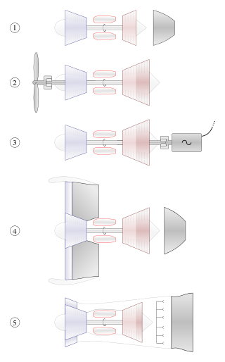
A gas turbine, also called a combustion turbine, is a type of continuous flow internal combustion engine. The main parts common to all gas turbine engines form the power-producing part and are, in the direction of flow:

<span class="mw-page-title-main">Exhaust gas recirculation</span> NOx reduction technique used in gasoline and diesel engines

In internal combustion engines, exhaust gas recirculation (EGR) is a nitrogen oxide (NOx) emissions reduction technique used in petrol/gasoline, diesel engines and some hydrogen engines. EGR works by recirculating a portion of an engine's exhaust gas back to the engine cylinders. The exhaust gas displaces atmospheric air and reduces O2 in the combustion chamber. Reducing the amount of oxygen reduces the amount of fuel that can burn in the cylinder thereby reducing peak in-cylinder temperatures. The actual amount of recirculated exhaust gas varies with the engine operating parameters.

<span class="mw-page-title-main">Four-stroke engine</span> Internal combustion engine type

A four-strokeengine is an internal combustion (IC) engine in which the piston completes four separate strokes while turning the crankshaft. A stroke refers to the full travel of the piston along the cylinder, in either direction. The four separate strokes are termed:

  1. Intake: Also known as induction or suction. This stroke of the piston begins at top dead center (T.D.C.) and ends at bottom dead center (B.D.C.). In this stroke the intake valve must be in the open position while the piston pulls an air-fuel mixture into the cylinder by producing a partial vacuum in the cylinder through its downward motion.
  2. Compression: This stroke begins at B.D.C, or just at the end of the suction stroke, and ends at T.D.C. In this stroke the piston compresses the air-fuel mixture in preparation for ignition during the power stroke (below). Both the intake and exhaust valves are closed during this stage.
  3. Combustion: Also known as power or ignition. This is the start of the second revolution of the four stroke cycle. At this point the crankshaft has completed a full 360 degree revolution. While the piston is at T.D.C. the compressed air-fuel mixture is ignited by a spark plug or by heat generated by high compression, forcefully returning the piston to B.D.C. This stroke produces mechanical work from the engine to turn the crankshaft.
  4. Exhaust: Also known as outlet. During the exhaust stroke, the piston, once again, returns from B.D.C. to T.D.C. while the exhaust valve is open. This action expels the spent air-fuel mixture through the exhaust port.
<span class="mw-page-title-main">Brayton cycle</span> Thermodynamic cycle

The Brayton cycle is a thermodynamic cycle that describes the operation of certain heat engines that have air or some other gas as their working fluid. The original Brayton engines used a piston compressor and piston expander, but modern gas turbine engines and airbreathing jet engines also follow the Brayton cycle. Although the cycle is usually run as an open system, it is conventionally assumed for the purposes of thermodynamic analysis that the exhaust gases are reused in the intake, enabling analysis as a closed system.

<span class="mw-page-title-main">British Rail 18000</span>

British Rail 18000 was a prototype mainline gas turbine-electric locomotive built for British Railways in 1949 by Brown, Boveri & Cie. An earlier gas-turbine locomotive, 18100, had been ordered from Metropolitan-Vickers by the Great Western Railway but construction was delayed due to World War II; a second, 18000, was thus ordered from Switzerland in 1946. It spent its working life on the Western Region of British Railways, operating express passenger services from Paddington station, London.

<span class="mw-page-title-main">Gas turbine locomotive</span> Type of railway locomotive

A gas turbine locomotive is a type of railway locomotive in which the prime mover is a gas turbine. Several types of gas turbine locomotive have been developed, differing mainly in the means by which mechanical power is conveyed to the driving wheels (drivers). A gas turbine train typically consists of two power cars, and one or more intermediate passenger cars.

<span class="mw-page-title-main">Gas engine</span>

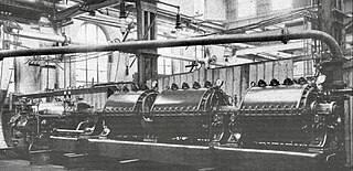
A gas engine is an internal combustion engine that runs on a gaseous fuel, such as coal gas, producer gas, biogas, landfill gas, natural gas or hydrogen. In the United Kingdom and British English-speaking countries, the term is unambiguous. In the United States, due to the widespread use of "gas" as an abbreviation for gasoline (petrol), such an engine might also be called a gaseous-fueled engine or natural gas engine or spark ignited.

<span class="mw-page-title-main">Hot-bulb engine</span> Internal combustion engine

The hot-bulb engine is a type of internal combustion engine in which fuel ignites by coming in contact with a red-hot metal surface inside a bulb, followed by the introduction of air (oxygen) compressed into the hot-bulb chamber by the rising piston. There is some ignition when the fuel is introduced, but it quickly uses up the available oxygen in the bulb. Vigorous ignition takes place only when sufficient oxygen is supplied to the hot-bulb chamber on the compression stroke of the engine.

<span class="mw-page-title-main">Turbo-diesel</span> Diesel engine with a turbocharger

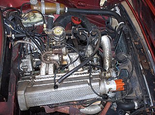
The term turbo-diesel, also written as turbodiesel and turbo diesel, refers to any diesel engine equipped with a turbocharger. As with other engine types, turbocharging a diesel engine can significantly increase its efficiency and power output, especially when used in combination with an intercooler.

Engine efficiency of thermal engines is the relationship between the total energy contained in the fuel, and the amount of energy used to perform useful work. There are two classifications of thermal engines-

  1. Internal combustion and
  2. External combustion engines.
<span class="mw-page-title-main">Union Pacific GTELs</span> Fleet of gas turbine-electric locomotives

The Union Pacific GTELs were a series of gas turbine-electric locomotives built by Alco-GE and General Electric between 1952-1961 and operated by Union Pacific from 1952 to 1970.

<span class="mw-page-title-main">Engine-generator</span> Combination of an electrical generator and an engine in a single part

An engine–generator is the combination of an electrical generator and an engine mounted together to form a single piece of equipment. This combination is also called an engine–generator set or a gen-set. In many contexts, the engine is taken for granted and the combined unit is simply called a generator. An engine–generator may be a fixed installation, part of a vehicle, or made small enough to be portable.

<span class="mw-page-title-main">Free-piston engine</span>

A free-piston engine is a linear, 'crankless' internal combustion engine, in which the piston motion is not controlled by a crankshaft but determined by the interaction of forces from the combustion chamber gases, a rebound device and a load device.

Internal combustion engines come in a wide variety of types, but have certain family resemblances, and thus share many common types of components.

<span class="mw-page-title-main">Internal combustion engine</span> Engine in which the combustion of a fuel occurs with an oxidizer in a combustion chamber

An internal combustion engine is a heat engine in which the combustion of a fuel occurs with an oxidizer in a combustion chamber that is an integral part of the working fluid flow circuit. In an internal combustion engine, the expansion of the high-temperature and high-pressure gases produced by combustion applies direct force to some component of the engine. The force is typically applied to pistons, turbine blades, a rotor, or a nozzle. This force moves the component over a distance, transforming chemical energy into kinetic energy which is used to propel, move or power whatever the engine is attached to.

<span class="mw-page-title-main">Velox boiler</span>

A Velox boiler is a turbocharged, forced circulation, water-tube boiler which utilises an axial flow compressor and a gas turbine. Velox boilers, also known as Velox steam generators, were developed in the early 1930s by the Brown Boveri Company (BBC) of Switzerland. Velox boilers were the first commercially available machines to make use of axial compressors and played a pivotal role in the later development of BBC’s industrial gas turbines.

<span class="mw-page-title-main">Internal combustion locomotive</span> Railway locomotive that produces its pulling power through an internal combustion engine

An internal combustion locomotive is a type of railway locomotive that produces its pulling power using an internal combustion engine. These locomotives are fuelled by burning fossil fuels, most commonly oil or gasoline, to produce rotational power which is transmitted to the locomotive's driving wheels by various direct or indirect transmission mechanisms. The fuel is carried on the locomotive.

<span class="mw-page-title-main">Armengaud-Lemale gas turbine</span>

The Armengaud-Lemale gas turbine was an early experimental turbine engine built by the Société Anonyme des Turbomoteurs and exibited during 1906 in Paris, France. The gas turbine could sustain its own air compression but was too inefficient to produce useful work. The Armengaud-Lemale combustion chamber design was later used successfully in torpedo engines.

References

  1. 1 2 3 4 5 6 7 8 9 10 11 12 13 Meyer, Adolf (May 1942). "The First Gas Turbine Locomotive" (PDF). The Brown Boveri Review. pp. 1–28.
  2. 1 2 Keller, Rolf (March 1975). "Gas Turbine Drive for New High Speed Trains". Gas Turbine Division of The American Society of Mechanical Engineers for presentation at the Gas Turbine Conference & Products Show, Houston, Texas, March 2-6, 1975.: 1. doi:10.1115/75-gt-88.
  3. 1 2 3 "Locomotive dimenticate A m 4 / 6 La prima locomotiva a turbina a gas del mondo" (in Italian). Retrieved 2022-11-16.
  4. Brun, Klaus; Kurz, Rainer (2019). Introduction to Gas Turbine Theory (4 ed.). Solar Turbines Incorporated. p. 15. ISBN   978-0-578-48386-3.