Turbo transmissions are hydrodynamic, multi-stage drive assemblies designed for rail vehicles using internal combustion engines. The first turbo-transmission was developed in 1932 by Voith in Heidenheim, Germany. Since then, improvements to turbo-transmissions have paralleled similar advances in diesel motors and today this combination plays a leading role worldwide, second only to the use of electrical drives.
Turbo transmissions serve as a hydrodynamic link which converts a motor's mechanical energy into the kinetic energy of a fluid, via a torque-converter and fluid coupling, before producing the final rotary output. Here, the fluid is driven through rotor blade canals at high flow rates and low pressure. This is where turbo-transmissions differ from similar hydro-statictransmissions, which operate using low flow rates, and high pressure according to the displacement principle.
Principle
Turbo transmissions are hydrodynamic, multi-stage drive assemblies whose performance is based on the Föttinger principle of fluid dynamics. Torque converters, fluid couplings and optional hydrodynamic retarders are the key components in these assemblies, which are ideally suited for powered rail vehicles.
History
The first turbo transmission from 1932 used a relatively simple design. It consisted of a single torque converter for the start-up phase and a fluid coupling for the travel phase which were both mounted on a common shaft. A key feature of this turbo transmission was the filling and emptying of the hydrodynamic circuit, a principle which was first used in Föttinger marine transmissions. This offered the advantages of frictionless start-ups, frictionless gear shifting with constant traction, freewheeling through emptying of the hydrodynamic circuit, and more efficient operation of the fluid coupling.
Contrary to Föttinger however, Voith used low viscosity oil in the hydrodynamic circuit of its turbo-transmissions rather than water. In addition, various other improvements were made in the 1930s: The addition of a high-speed gear, a more compact housing, greater compatibility with different motor types, automation gear shifts, as well as cooling via a heat exchanger.
In the 1960s the hydrodynamic retarder was also introduced as a third stage which complemented the torque-converter and fluid coupling. Together, all these engineering improvements had a common goal: to continually increase the transmission's performance rating without compromising its installation complexity or proven reliability.
Double circuit transmissions for railcars
In 1969, the smaller T 211 turbo-transmission was developed as an alternative to hydro-mechanical bus transmissions, being designed for diesel railcars in the low power range of 200 to 300hp (149 to 224kW). Similar to the first turbo-transmission, the T 211 used a linked converter-coupling combination but it also had a high-speed gear for greater efficiency. Additionally, a reversing gear assembly was added and an optional hydrodynamic retarder could be installed if required. The converter had a hydrodynamic circuit diameter of 346mm (13.6in), while the fluid coupling had a slightly smaller diameter of 305mm (12.0in). And due to its high-speed gear, the main shaft could run significantly higher at 4,170 rpm. As a result, the T 211 r had reserve power, which was reflected by its reinforced mechanical components (gears, bearings and shafts) as well as the transmission controls. At the same time however, the diameters of the converter, coupling and retarder remained unchanged. The overall flow rate within the hydrodynamic circuits was increased to accommodate the higher power rating of 205 to 350kW (275 to 469hp). At 350kW (469hp), the main shaft ran at just under 5,000 rpm which resulted in rotational speeds for the (empty) converter of 74m/s when the vehicle reached its maximum speed. To ensure adequate cooling of the converter during high-speed operations, a stronger hydrodynamic fluid pump was installed, which supplied 3.5 L/s of oil through the heat exchanger during the travel phase and 9.0 L/s when in the braking phase, with the retarder rotor also serving as an additional circulating pump. When viewed from the outside this T 211 r transmission differed from its predecessor, the T 211 re.3 with 320kW (429hp), only slightly through the addition of a built-in electronic control unit and an enlarged air filter.
Also in 1978 there was a new type of hydraulic gearbox for trains, the T320RZ + KB260 + HA
Triple circuit transmissions for railcars
In 1995, an entirely new transmission design was developed, the VT 611/612, for high-speed trains with tilting technology used by the Deutsche Bahn (German Railways). This new transmission concept used a converter-coupling-coupling design with an integrated hydrodynamic T 312 bre retarder and it had a power rating of 650kW. To shorten the transmission's overall length, a twin shaft construction was used over the high gears, which was similar to the design used in reversing units. The electronic control unit was also built into the transmission. In addition, the transmission's reversing cylinders were operated hydraulically, which eliminated the need of having a compressed air supply on board. Five years later, the T 212 bre transmission was developed with a power rating of 460kW. This transmission was similar in design, but unlike other large transmissions the T 212 bre could be mounted directly on the drive motor. This was a significant advantage, because it resulted in a very compact motor-transmission combination for high-speed trains which could travel at up to 200km/h. The T 212 bre had the same hydrodynamic circuit dimensions as the T 211 r, but it had the further advantage of greater coupling efficiency for trains operating at only 50% of their maximum speed. For high-speed diesel trains this was important, because it permitted dramatically improved fuel consumption.
Twin converter transmissions for locomotives
In 1999, a new twin converter transmission, the L 620 reU2, was developed for high-performance, main-line locomotives. The new L 620 reU2 was equipped with both a start-up converter, having a diameter of 525mm, as well as a travel-phase converter, having a diameter of 434mm. The design of the new L 620 re U2 was based on its successful predecessor, the L 520 rzU2 which had a power rating of 1,400kW. This new transmission however was rated significantly higher at 2,700kW and therefore virtually all of its components had to be enlarged as well as reinforced. In the standard version of the transmission, two gears were mounted on the secondary shaft rather than using the idler wheel found in the older L 520 rzU2. As a result, the drive shaft's output speed could be adjusted to suit the locomotive's power requirements. The drive shaft's main bearing was also enlarged to 550mm. In general, this new high-performance transmission clearly illustrated the enormous capability of hydrodynamic couplings. With a weight-to-power ratio of only 2.06kg/kW, the new L 620 reU2 set a record for locomotive transmissions. By comparison, the similar L 520 rzU2 transmission had a far higher weight-to-power ratio of 2.4kg/kW. In addition, a newly designed hydrodynamic retarder, the KB 385, was available as an optional component. At Vossloh, the locomotive manufacturer based in Kiel, these transmissions were installed in both its G1700 and G2000 main-line locomotives. Finally, the latest development is the LS 640 reU2 transmission which will be used for the first time in the Voith Maxima locomotive having 3,600kW. The LS 640 reU2 is a so-called split turbo-transmission which uses two drive shafts from the L 620 reU2 to power both bogies of a six axle diesel locomotive.
Setting performance standards of turbo-transmissions
The operating conditions of rail vehicles are the key factors in determining the power requirements of both its motors and transmissions. These operating conditions cover: hauling loads for diesel locomotive, passenger capacities for diesel rail-cars, the topography of the rail line, and the climatic conditions when the vehicle is operated outside of Europe. The expected operating conditions are part of a vehicle's technical requirements and determine the follow points:
Maximum speed
Acceleration rates during start-up in consideration of the frictional resistance of all motorized wheel-sets in multi car trains
Acceleration rates when in transit to avoid traffic jams in metropolitan areas where predominantly electric rail-cars are also in operation
Minimum speed which can be maintained over long distances
Dynamic braking requirements when travelling at high-speeds and/or over long descents due to its economical operation
Maximum speed, vehicle weight, acceleration rate and the railway slope all influence a motor's performance specifications. Added to that, the requirements of the auxiliary systems also need to be considered, such air-conditioning units, motor cooling systems, brake compressors and in some cases the need for a separate power supply to run the air-conditioning and heating systems of each passenger car. Here, a range of diesel motors can be selected, from large frame V-motors for locomotives to flat 6-cylinder sub-floor motors for motorized railcars or even the compact 12-cylinder motors often used by utility vehicles. For most modern motorized railcars, the preferred solution is a sub-floor mounted motor and transmission combination.
Advanced development of torque converters
In turbo transmissions, the torque converter is clearly the centerpiece of the entire construction and over the past decades its continuous improvements have been primarily responsible for satisfying the steadily increasing demands of diesel powered vehicles. Here, the goal of each improvement has been greater efficiency and better start-up performance, without compromising the start-up converter's dimensions as well as consistent loading of the travel-phase converter when in transit. Of the many different torque-converter designs, the single-stage converter using a centrifugal-flow turbine has proven to be the best. It has a relatively simple construction and due to the radial stability of its turbine the converter is well suited for high rpm operations.
In the 1970s, thanks to new torque-converter developments with improved traction characteristics, (approaching the start-up traction) a two-converter transmission was designed to replace the previously used three-converter transmission. And even today, torque-converters are still being improved, although they have reached an advanced stage. Modern computational fluid dynamics (CFD) can now provide engineers with detailed information on the flow-patterns inside a rotating turbine wheel. Here, the oil-filled circuit in which the turbine turns is portrayed as computerized grid showing the flow characteristics at each grid intersection. For each of these points, the flow volume, speed, and pressure can be calculated. Later during the analysis phase, a three dimensional model of the circuit's flow pattern can be viewed and flow disruptions which reduce the converter's efficiency can be identified, such as: eddies, surface turbulence and mis-directed fluid-flows along the turbine wheel. In addition, aside from visualizing these flow disruptions engineers can also use CFD to calculate the resultant loss in converter efficiency.
In the end, the relationship between changes in a converter circuit's flow-patterns and the efficiency of a torque-converter can then be used to identify potential improvement areas. To a large extent, the predicted values match well with the actual operational measurements, although some differences do occur due to the use of time-saving simplified simulations. Still, CFD allows the optimization of existing converters as well as the development of new virtual-converter types via computer. Afterwards the building of a prototype and the verification of the actual performance results concludes the development phase.
Dinet.biz Alternative spare parts for Voith gearbox buses
Related Research Articles
An automatic transmission is a multi-speed transmission used in motor vehicles that does not require any input from the driver to change forward gears under normal driving conditions. Vehicles with internal combustion engines, unlike electric vehicles, require the engine to operate in a narrow range of rates of rotation, requiring a gearbox, operated manually or automatically, to drive the wheels over a wide range of speeds.
Dynamic braking is the use of an electric traction motor as a generator when slowing a vehicle such as an electric or diesel-electric locomotive. It is termed "rheostatic" if the generated electrical power is dissipated as heat in brake grid resistors, and "regenerative" if the power is returned to the supply line. Dynamic braking reduces wear on friction-based braking components, and regeneration lowers net energy consumption. Dynamic braking may also be used on railcars with multiple units, light rail vehicles, electric trams, trolleybuses, and electric and hybrid electric automobiles.
A torque converter is a device, usually implemented as a type of fluid coupling, that transfers rotating power from a prime mover, like an internal combustion engine, to a rotating driven load. In a vehicle with an automatic transmission, the torque converter connects the prime mover to the automatic gear train, which then drives the load. It is thus usually located between the engine's flexplate and the transmission. The equivalent device in a manual transmission is the mechanical clutch.
A diesel–electric transmission, or diesel–electric powertrain, is a transmission system for vehicles powered by diesel engines in road, rail, and marine transport. Diesel–electric transmission is based on petrol–electric transmission, a transmission system used for petrol engines.
A traction motor is an electric motor used for propulsion of a vehicle, such as locomotives, electric or hydrogen vehicles, or electric multiple unit trains.
A motor–generator is a device for converting electrical power to another form. Motor–generator sets are used to convert frequency, voltage, or phase of power. They may also be used to isolate electrical loads from the electrical power supply line. Large motor–generators were widely used to convert industrial amounts of power while smaller motor–generators were used to convert battery power to higher DC voltages.
Hydraulic machines use liquid fluid power to perform work. Heavy construction vehicles are a common example. In this type of machine, hydraulic fluid is pumped to various hydraulic motors and hydraulic cylinders throughout the machine and becomes pressurized according to the resistance present. The fluid is controlled directly or automatically by control valves and distributed through hoses, tubes, or pipes.
Hydramatic is an automatic transmission developed by both General Motors' Cadillac and Oldsmobile divisions. Introduced in 1939 for the 1940 model year vehicles, the Hydramatic was the first mass-produced fully-automatic transmission developed for passenger automobile use.
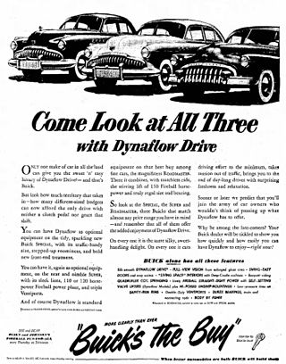
Dynaflow was the trademarked name for a type of automatic transmission developed and built by General Motors Buick Motor Division from late 1947 to mid-1963. The Dynaflow, which was introduced for the 1948 model year only as an option on Roadmaster models, received some severe early testing in the M18 Hellcat tank destroyer, which were built in Buick's Flint Assembly plant during World War II. It was also used in the 1951 Le Sabre concept car.
Turbo-Hydramatic or Turbo Hydra-Matic is the registered tradename for a family of automatic transmissions developed and produced by General Motors. These transmissions mate a three-element turbine torque converter to a Simpson planetary geartrain, providing three forward speeds plus reverse.
Roto Hydramatic was an automatic transmission built by General Motors and used in some Oldsmobile, Pontiac and Holden models between 1961 and 1965. It was based on the earlier, four-speed Hydramatic, but was more compact, providing only three forward speeds plus a small 8" fluid coupling with a stator inside of the fluid coupling. Oldsmobile, one of the companies that used this transmission in some of its cars, called the fluid couplings stator the "Accel-A-Rotor." The lightweight, aluminum-cased transmission was sometimes nicknamed the "Slim Jim." HydraMatic Division calls the Roto a four-range, three-gear HydraMatic.
A fluid coupling or hydraulic coupling is a hydrodynamic or 'hydrokinetic' device used to transmit rotating mechanical power. It has been used in automobile transmissions as an alternative to a mechanical clutch. It also has widespread application in marine and industrial machine drives, where variable speed operation and controlled start-up without shock loading of the power transmission system is essential.
The Voith Group is a German multinational technology company with a broad portfolio of systems, products, services and digital applications. Voith works in the markets of energy, paper, raw materials and transport & automotive. Founded in 1867, the company today has around 22,479 employees, sales of €5.5 billion and locations in over 60 countries worldwide and is thus one of the larger family-owned companies in Europe.
A retarder is a device used to augment or replace some of the functions of primary friction-based braking systems, usually on heavy vehicles. Retarders serve to slow vehicles, or maintain a steady speed while traveling down a hill, and help prevent the vehicle from "running away" by accelerating down the hill. They are not usually capable of bringing vehicles to a standstill, as their effectiveness diminishes as vehicle speed lowers. They are usually used as an additional "assistance" to slow vehicles, with the final braking done by a conventional friction braking system. As the friction brake will be used less, particularly at higher speeds, their service life is increased, and since in those vehicles the brakes are air-actuated helps to conserve air pressure too.
The Turboglide is a Chevrolet constant torque, continuously variable automatic transmission first offered as an option on Chevrolet V8 passenger cars for 1957. It consisted of a turbine-driven planetary gearbox with a 'switch pitch' dual-pitch torque converter stator. It had a die-cast aluminum transmission case, like Packard's Ultramatic of 1956. Turboglide cost about $50 more than the Powerglide 2-speed automatic. It was available in all V8-powered 1957-1961 Chevrolet models except the Corvette. General Motors produced 646,000 of these transmissions during its production.
The Paxman Hi-Dyne engine was a form of experimental diesel engine developed for rail transport use by the British engine makers Paxman of Colchester. They used variable supercharging to give a constant power output across their speed range.
A drivetrain is the group of components that deliver mechanical power from the prime mover to the driven components. In automotive engineering, the drivetrain is the components of a motor vehicle that deliver power to the drive wheels. This excludes the engine or motor that generates the power. In marine applications, the drive shaft will drive a propeller, thruster, or waterjet rather than a drive axle, while the actual engine might be similar to an automotive engine. Other machinery, equipment and vehicles may also use a drivetrain to deliver power from the engine(s) to the driven components.
SNCF BB 69000 were a pair of two prototype high-power diesel-hydraulic locomotives, numbered BB 69001 and BB 69002. They were built at the same time, and for comparison with, as a diesel-electric version, CC 70000. The use of hydraulic transmission saved 30 tons in weight and enabled the locomotives to run on four axles instead of the six axles of the diesel-electric.
CFR Series 040 DH are locomotives produced in large numbers, equipped with a hydrodynamic power transmission. They were used for shunting and light mainline service by the Romanian state railways CFR. In addition, 475 locomotives of this type were delivered to Romanian industrial companies, 263 units were delivered to Bulgaria, 42 units were delivered to industrial companies in Czechoslovakia, three units went to Iraq, two units went to China and one unit was delivered to the USSR.
This page is based on this Wikipedia article Text is available under the CC BY-SA 4.0 license; additional terms may apply. Images, videos and audio are available under their respective licenses.