Anchor bolt

Last updated
Column-to-foundation connection Steel To Concrete Base Plate.png
Column-to-foundation connection

Anchor bolts are used to connect structural and non-structural elements to concrete. [2] The connection can be made by a variety of different components: anchor bolts (also named fasteners), steel plates, or stiffeners. Anchor bolts transfer different types of load: tension forces and shear forces. [3]

Contents

A connection between structural elements can be represented by steel columns attached to a reinforced concrete foundation. [4] A common case of a non-structural element attached to a structural one is the connection between a facade system and a reinforced concrete wall. [5]

Types

Type of anchors Types Of Anchors.png
Type of anchors

Cast-in-place

A cast-in-place anchor bolt Anchor bolt in concrete.jpg
A cast-in-place anchor bolt

The simplest and strongest form of anchor bolt is cast-in-place, with its embedded end consisting of a standard hexagonal head bolt and washer, 90-bend, or some sort of forged or welded flange (see also stud welding). The last are used in concrete-steel composite structures as shear connectors. [6] Other uses include anchoring machines to poured concrete floors [7] and buildings to their concrete foundations. Various typically disposable aids, mainly of plastic, are produced to secure and align cast-in-place anchors prior to concrete placement. Moreover, their position must also be coordinated with the reinforcement layout. [3] Different types of cast-in-place anchors might be distinguished: [3]

For all the type of the cast-in-place anchors, the load-transfer mechanisms is the mechanical interlock, [3] i.e. the embedded part of the anchors in concrete transfers and the applied load (axial or shear) via bearing pressure at the contact zone. At failure conditions, the level of bearing pressure can be higher than 10 times the concrete compressive strength, if a pure tension force is transferred. [3] Cast-in-place type anchors are also utilized in masonry applications, placed in wet mortar joints during the laying of brick and cast blocks (CMUs).

Post-installed

Post-installed anchors can be installed in any position of hardened concrete after a drilling operation. [3] A distinction is made according to their principle of operation.

Mechanical expansion anchors

A wedge anchor Expansion bolt cutaway.jpg
A wedge anchor

The force-transfer mechanism is based on friction mechanical interlock guaranteed by expansion forces. They can be further divided into two categories: [3]

  • torque controlled: the anchor is inserted into the hole and secured by applying a specified torque to the bolt head or nut with a torque wrench. A particular sub-category of this anchor is called wedge type. As shown in the figure, tightening the bolt results in a wedge being driven up against a sleeve, which expands it and causes it to compress against the material it is being fastened to.
  • displacement controlled: usually consist of an expansion sleeve and a conical expansion plug, whereby the sleeve is internally threaded to accept a threaded element.

Undercut anchors

The force-transfer mechanism is based on mechanical interlock. A special drilling operation allows to create a contact surface between the anchor head and the hole's wall where bearing stresses are exchanged.

Bonded anchors

A bonded anchor Varilla roscada y anclaje quimico.jpg
A bonded anchor

Bonded anchors are also referred as adhesive anchors [9] or chemical anchors. The anchoring material is an adhesive (also called mortar) [3] usually consisting of epoxy, polyester, or vinylester resins. [1]

In bonded anchors, the force-transfer mechanism is based on bond stresses provided by binding organic materials. Both ribbed bars and threaded rods can be used and a change of the local bond mechanism can be appreciated experimentally. In ribbed bars the resistance is prevalently due to shear behavior of concrete between the ribs whereas for threaded rods friction prevails (see also anchorage in reinforced concrete). [10]

The performance of this anchor's types in terms of 'load-bearing capacity', especially under tension loads, is strictly related to the cleaning condition of the hole. Experimental results [3] showed that the reduction of the capacity is up to 60%. The same applies also for moisture condition of concrete, for wet concrete the reduction is of 20% using polyester resin. Other issues are represented by high temperature behavior [11] and creep response. [12]

Screw anchors

The force-transfer mechanism of the screw anchor is based on concentrated pressure exchange between the screw and concrete through the pitches.

Plastic anchors

Plastic anchors Wall plugs plastic.jpg
Plastic anchors

Their force-transfer mechanism is similar to mechanical expansion anchors. A torque moment is applied to a screw which is inserted in a plastic sleeve. As the torque is applied the plastic expands the sleeve against the sides of the hole acting as expansion force.

Tapcon screws

Tapcon screws are a popular anchor that stands for self tapping (self threading) concrete screw. Larger diameter screws are referred to as LDT's. This type of fastener requires a pre-drilled hole—using a Tapcon drillbit—and are then screwed into the hole using a standard hex or phillips bit. These screws are often blue, white, or stainless. [13] They are also available in versions for marine or high stress applications.

Powder-actuated anchors

They act transferring the forces via mechanical interlock. This fastening technology is used in steel-to-steel connection, for instance to connect cold-formed profiles. A screw is inserted into the base material via a gas actuated gas gun. The driving energy is usually provided by firing a combustible propellant in powder form. [14] The fastener's insertion provokes the plastic deformation of the base material which accommodates the fastener's head where the force transfer takes place.

Mechanical behavior

Modes of failure in tension

Anchors can fail in different way when loaded in tension: [3]

In design verification under ultimate limit state, codes prescribe to verify all the possible failure mechanisms. [18]

Modes of failure in shear

Anchors can fail in different way when loaded in shear: [3]

In design verification under ultimate limit state, codes prescribe to verify all the possible failure mechanisms. [18]

Combined tension/shear

When contemporarily tension and shear load are applied to an anchor the failure occurs earlier (at a less load-bearing capacity) with respect the un-coupled case. In current design codes a linear interaction domain is assumed. [20]

Group of anchors

Group of two bonded anchors with overlapping concrete cones Overlapping Cones.png
Group of two bonded anchors with overlapping concrete cones

In order to increase the load-carrying capacity anchors are assembled in group, moreover this allow also to arrange a bending moment resisting connection. For tension and shear load, the mechanical behavior is markedly influenced by (i) the spacing between the anchors and (ii) the possible difference in the applied forces. [22]

Service load behavior

Under service loads (tension and shear) anchor's displacement must be limited. The anchor performance (load-carrying capacity and characteristic displacements) under different loading condition is assessed experimentally, then an official document is produced by technical assessment body. [23] In design phase, the displacement occurring under the characteristic actions should be not larger than the admissible displacement reported in the technical document.

Seismic load behavior

Under seismic loads and there would be the possibility that an anchor is contemporarily (i) installed in a crack and (ii) subjected to inertia loads proportional both to the mass and the acceleration of the attached element (secondary structure) to the base material (primary structure). [2] The load conditions in this case can be summarized as follow:

Exceptional loads behavior

Exceptional loads differ from ordinary static loads for their rise time. High displacement rates are involved in impact loading. Regarding steel to concrete connections, some examples consist in collision of vehicle on barriers connected to concrete base and explosions. Apart from these extraordinary loads, structural connections are subjected to seismic actions, which rigorously have to be treated via dynamic approach. For instance, seismic pull-out action on anchor can have 0.03 seconds of rise time. On the contrary, in a quasi-static test, 100 second may be assumed as time interval to reach the peak load. Regarding the concrete base failure mode: Concrete cone failure loads increase with elevated loading rates with respect the static one. [25]

Designs

See also

Related Research Articles

<span class="mw-page-title-main">Rebar</span> Steel reinforcement

Rebar, known when massed as reinforcing steel or reinforcement steel, is a steel bar used as a tension device in reinforced concrete and reinforced masonry structures to strengthen and aid the concrete under tension. Concrete is strong under compression, but has low tensile strength. Rebar significantly increases the tensile strength of the structure. Rebar's surface features a continuous series of ribs, lugs or indentations to promote a better bond with the concrete and reduce the risk of slippage.

<span class="mw-page-title-main">Rivet</span> Permanent mechanical fastener

A rivet is a permanent mechanical fastener. Before being installed, a rivet consists of a smooth cylindrical shaft with a head on one end. The end opposite the head is called the tail. On installation, the rivet is placed in a punched or drilled hole, and the tail is upset or bucked, so that it expands to about 1.5 times the original shaft diameter, holding the rivet in place. In other words, the pounding or pulling creates a new "head" on the tail end by smashing the "tail" material flatter, resulting in a rivet that is roughly a dumbbell shape. To distinguish between the two ends of the rivet, the original head is called the factory head and the deformed end is called the shop head or buck-tail.

<span class="mw-page-title-main">Fastener</span> Hardware device that mechanically joins or affixes two or more objects together

A fastener or fastening is a hardware device that mechanically joins or affixes two or more objects together. In general, fasteners are used to create non-permanent joints; that is, joints that can be removed or dismantled without damaging the joining components. Steel fasteners are usually made of stainless steel, carbon steel, or alloy steel.

<span class="mw-page-title-main">Bolted joint</span> Mechanical joint secured by a threaded fastener

A bolted joint is one of the most common elements in construction and machine design. It consists of a male threaded fastener that captures and joins other parts, secured with a matching female screw thread. There are two main types of bolted joint designs: tension joints and shear joints.

<span class="mw-page-title-main">Seismic retrofit</span> Modification of existing structures to make them more resistant to seismic activity

Seismic retrofitting is the modification of existing structures to make them more resistant to seismic activity, ground motion, or soil failure due to earthquakes. With better understanding of seismic demand on structures and with our recent experiences with large earthquakes near urban centers, the need of seismic retrofitting is well acknowledged. Prior to the introduction of modern seismic codes in the late 1960s for developed countries and late 1970s for many other parts of the world, many structures were designed without adequate detailing and reinforcement for seismic protection. In view of the imminent problem, various research work has been carried out. State-of-the-art technical guidelines for seismic assessment, retrofit and rehabilitation have been published around the world – such as the ASCE-SEI 41 and the New Zealand Society for Earthquake Engineering (NZSEE)'s guidelines. These codes must be regularly updated; the 1994 Northridge earthquake brought to light the brittleness of welded steel frames, for example.

Earthquake engineering is an interdisciplinary branch of engineering that designs and analyzes structures, such as buildings and bridges, with earthquakes in mind. Its overall goal is to make such structures more resistant to earthquakes. An earthquake engineer aims to construct structures that will not be damaged in minor shaking and will avoid serious damage or collapse in a major earthquake. A properly engineered structure does not necessarily have to be extremely strong or expensive. It has to be properly designed to withstand the seismic effects while sustaining an acceptable level of damage.

<span class="mw-page-title-main">Steel frame</span> Building technique using skeleton frames of vertical steel columns

Steel frame is a building technique with a "skeleton frame" of vertical steel columns and horizontal I-beams, constructed in a rectangular grid to support the floors, roof and walls of a building which are all attached to the frame. The development of this technique made the construction of the skyscraper possible.

<span class="mw-page-title-main">Screw (simple machine)</span> Mechanism that converts motion, and forces, from rotational to linear

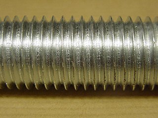
A screw is a mechanism that converts rotational motion to linear motion, and a torque to a linear force. It is one of the six classical simple machines. The most common form consists of a cylindrical shaft with helical grooves or ridges called threads around the outside. The screw passes through a hole in another object or medium, with threads on the inside of the hole that mesh with the screw's threads. When the shaft of the screw is rotated relative to the stationary threads, the screw moves along its axis relative to the medium surrounding it; for example rotating a wood screw forces it into wood. In screw mechanisms, either the screw shaft can rotate through a threaded hole in a stationary object, or a threaded collar such as a nut can rotate around a stationary screw shaft. Geometrically, a screw can be viewed as a narrow inclined plane wrapped around a cylinder.

Multi-jackbolt tensioners (MJT) are an alternative to traditional bolted joints. Rather than needing to tighten one large bolt, MJTs use several smaller jackbolts to significantly reduce the torque required to attain a certain preload. MJTs range in thread sizes from 34 in (19 mm) to 32 in (810 mm) and can achieve 20 million pounds-force or more. MJTs only require hand-held tools, such as torque wrenches or air/electric impacts, for loading and unloading bolted joints.

<span class="mw-page-title-main">Screw</span> Type of fastener characterized by a thread wrapped around a cylinder core

A screw and a bolt are similar types of fastener typically made of metal and characterized by a helical ridge, called a male thread.

ISO 898 is an international standard that defines mechanical and physical properties for metric fasteners. This standard is the origin for other standards that define properties for similar metric fasteners, such as SAE J1199 and ASTM F568M. It is divided into five (nonconsecutive) parts:

ASTM A325 is an ASTM International standard for heavy hex structural bolts, titled Standard Specification for Structural Bolts, Steel, Heat Treated, 120/105 ksi Minimum Tensile Strength. It defines mechanical properties for bolts that range from 12 to 1+12 inches in diameter.

ASTM A490 and ASTM A490M are ASTM International standards for heavy hex structural bolts made from alloy steel. The imperial standard is officially titled Standard Specification for Structural Bolts, Alloy Steel, Heat Treated, 150 ksi Minimum Tensile Strength, while the metric standard (M) is titled Standard Specification for High-Strength Steel Bolts, Classes 10.9 and 10.9.3, for Structural Steel Joints.

<span class="mw-page-title-main">Threaded rod</span> Rod with ridges wrapped around it

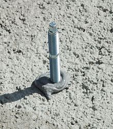
A threaded rod, also known as a stud, is a relatively long rod that is threaded on both ends; the thread may extend along the complete length of the rod. They are designed to be used in tension. Threaded rod in bar stock form is often called all-thread (ATR); other names include fully-threaded rod, redi-rod, continuously-threaded rod, and TFL rod.

A pipe support or pipe hanger is a designed element that transfer the load from a pipe to the supporting structures. The load includes the weight of the pipe proper, the content that the pipe carries, all the pipe fittings attached to pipe, and the pipe covering such as insulation. The four main functions of a pipe support are to anchor, guide, absorb shock, and support a specified load. Pipe supports used in high or low temperature applications may contain insulation materials. The overall design configuration of a pipe support assembly is dependent on the loading and operating conditions.

<span class="mw-page-title-main">Treehouse attachment bolt</span>

Treehouse attachment bolts or TABs are specialized bolts engineered for treehouse construction. Various models and trademarks exist, with names such as Garnier limbs (GLs); tree anchor bolts; artificial limbs; heavy limbs or hyper limbs (HLs); special tree fastener or stud tree fastener (STFs).

<span class="mw-page-title-main">Bolt (fastener)</span> Threaded fastener with an external male thread requiring a matching female thread

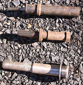
A bolt is a form of threaded fastener with an external male thread requiring a matching pre-formed female thread such as a nut. Bolts are very closely related to screws.

<span class="mw-page-title-main">Mechanical joint</span> Section of a machine which is used to connect one mechanical part to another

A mechanical joint is a section of a machine which is used to connect one or more mechanical part to another. Mechanical joints may be temporary or permanent; most types are designed to be disassembled. Most mechanical joints are designed to allow relative movement of these mechanical parts of the machine in one degree of freedom, and restrict movement in one or more others.

<span class="mw-page-title-main">Hybrid masonry</span>

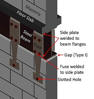
Hybrid masonry is a new type of building system that uses engineered, reinforced masonry to brace frame structures. Typically, hybrid masonry is implemented with concrete masonry panels used to brace steel frame structures. The basic concept is to attach a reinforced concrete masonry panel to a structural steel frame such that some combination of gravity forces, story shears and overturning moments can be transferred to the masonry. The structural engineer can choose from three different types of hybrid masonry and two different reinforcement anchorage types. In conventional steel frame building systems, the vertical force resisting steel frame system is supported in the lateral direction by steel bracing or an equivalent system. When the architectural plans call for concrete masonry walls to be placed within the frame, extra labor is required to ensure the masonry fits around the steel frame. Usually, this placement does not take advantage of the structural properties of the masonry panels. In hybrid masonry, the masonry panels take the place of conventional steel bracing, utilizing the structural properties of reinforced concrete masonry walls.

<span class="mw-page-title-main">Concrete cone failure</span> Failure mode of anchors in concrete submitted to tensile force

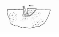
Concrete cone is one of the failure modes of anchors in concrete, loaded by a tensile force. The failure is governed by crack growth in concrete, which forms a typical cone shape having the anchor's axis as revolution axis.

References

  1. 1 2 3 4 5 6 7 8 9 10 Cook, Ronald; Doerr, G T; Klingner, R.E. (2010). Design Guide For Steel To Concrete Connections. University Of Texas Austin.
  2. 1 2 Hoehler, Matthew S.; Eligehausen, Rolf (2008). "Behavior and testing of anchors in simulated seismic cracks". ACI Structural Journal. 105 (3): 348–357. ISSN   0889-3241..
  3. 1 2 3 4 5 6 7 8 9 10 11 12 Mallèe, Rainer; Eligehausen, Rolf; Silva, John F (2006). Anchors In Concrete Structures. Ernst&Shon. ISBN   978-3433011430.
  4. Fisher, James M. (2006). Base Plate and Anchor Rod Design.
  5. IStructE (1988). Aspects of Cladding. London.{{cite book}}: CS1 maint: location missing publisher (link)
  6. Standard Handbook of Engineering Calculations. McGraw-Hill. 2004.
  7. Bhantia, K.G. (2008). Foundations for Industrial Machines – Handbook for practising engineering. New Delhi: D-CAD. ISBN   978-81-906032-0-1.
  8. Bachmann, Hubert; Steinle, Alfred (2012). Precast Concrete Structures. Berlin: Ernst&Shon. ISBN   978-0-7506-5084-7.
  9. Sasse, H.R. (1986). Adhesion between polymers and concrete. Springer. ISBN   978-0-412-29050-3.
  10. Reinhardt, Hans-Wolf (1982). Concrete under impact loading tensile strength and bond. Delft: Delft University.
  11. Raouffard, Mohammad Mahdi; Nishiyama, Minehiro (2018). "Idealization of bond stress-slip relationship at elevated temperatures based on pullout tests". ACI Structural Journal. 115 (2). doi:10.14359/51701120. ISSN   0889-3241.
  12. Nilforoush, Rasoul; Nilsson, Martin; Söderlind, Gunnar; Elfgren, Lennart (2016). "Long-Term Performance of Adhesive Bonded Anchors". ACI Structural Journal. 113 (2): 251–262. doi:10.14359/51688060..
  13. All About Tapcon Screws; Do It Yourself website online; accessed April 2019
  14. Beck, Hermann; Siemers, Michael; Reuter, Martin (2011). Powder-actuared fasteners and fastening screws in steel construction. Ernst&Shon. ISBN   978-3-433-02955-8.
  15. Eligehausen, Rolf; Sawade, G. (1989). "A fracture mechanics based description of the pull-out behavior of headed studs embedded in concrete". Fracture Mechanics of Concrete Structures: 281–299. doi:10.18419/opus-7930.
  16. Bungey, J.H.; Millard, S.G. (1996). Testing of Concrete in Structures. London: Blackie Academic & Professional. ISBN   0-203-48783-4.
  17. Stone, William C.; Carino, Nicholas J (1984). "Deformation and Failure in Large-Scale Pullout Tests". ACI Structural Journal (80).
  18. 1 2 ACI (2014). ACI 318-14 Building code requirements for structural concrete. Vol. 22. American Concrete Institute. ISBN   978-0-87031-930-3. JSTOR   3466335.
  19. Anderson, Neal S; Meinheit, Donald F (2005). "Pryout Capacity of Cast-In Headed Stud Anchors". PCI Journal. 50 (2): 90–112. doi:10.15554/pcij.03012005.90.112. ISSN   0887-9672.
  20. ACI (2004). "ACI 349.2 Guide to the Concrete Capacity Design ( CCD ) Method — Embedment Design Examples". Concrete (Ccd): 1–77.
  21. Doerr, G T; Klingner, R.E. (1989). Adhesive Anchors Behaviour And Spacing Requirements. University Of Texas Austin.
  22. Mahrenholtz, Philipp; Eligehausen, Rolf (2010). Behavior of anchor groups installed in cracked concrete under simulated seismic actions (PDF). Proceeding of the Conference on Fracture Mechanics of Concrete Structures (FraMCoS 7). Jeju, S. Korea.
  23. "How to find a TAB". EOTA. Archived from the original on 2018-06-14. Retrieved 2018-06-14.
  24. Fardis, Michael N. (2009). Seismic Design, Assessment and Retrofitting of Concrete Buildings. London: Springer. ISBN   978-1-4020-9841-3.
  25. Solomos, George. Testing of Anchorages in Concrete under Dynamic Loading. Ispra: Joint research Centre.

[1]

  1. "ETA seismic approval concrete screw". Joker Industrial.