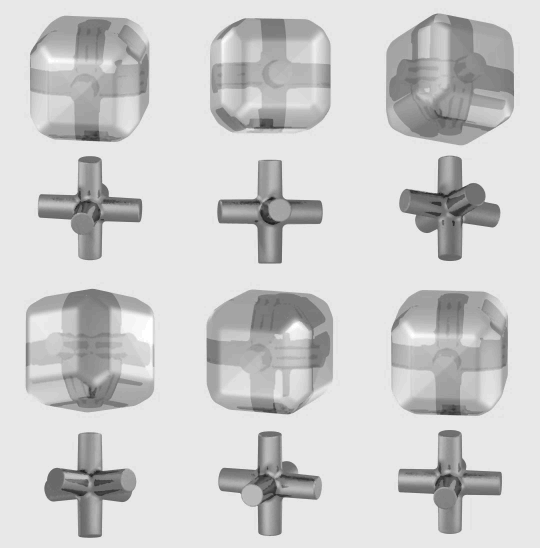
Computer-aided design (CAD) is the use of computers to aid in the creation, modification, analysis, or optimization of a design. This software is used to increase the productivity of the designer, improve the quality of design, improve communications through documentation, and to create a database for manufacturing. Designs made through CAD software are helpful in protecting products and inventions when used in patent applications. CAD output is often in the form of electronic files for print, machining, or other manufacturing operations. The terms computer-aided drafting (CAD) and computer aided design and drafting (CADD) is also used.

Computer-aided engineering (CAE) is the broad usage of computer software to aid in engineering analysis tasks. It includes finite element analysis (FEA), computational fluid dynamics (CFD), multibody dynamics (MBD), durability and optimization. It is included with computer-aided design (CAD) and computer-aided manufacturing (CAM) in the collective abbreviation "CAx".

Solid modeling is a consistent set of principles for mathematical and computer modeling of three-dimensional solids. Solid modeling is distinguished from related areas of geometric modeling and computer graphics, such as 3D modeling, by its emphasis on physical fidelity. Together, the principles of geometric and solid modeling form the foundation of 3D-computer-aided design and in general support the creation, exchange, visualization, animation, interrogation, and annotation of digital models of physical objects.

In industry, Product Lifecycle Management (PLM) is the process of managing the entire lifecycle of a product from its inception through the engineering, design and manufacture, as well as the service and disposal of manufactured products. PLM integrates people, data, processes and business systems and provides a product information backbone for companies and their extended enterprises.

SolidWorks is a solid modeling computer-aided design (CAD) and computer-aided engineering (CAE) application published by Dassault Systèmes.
Product and manufacturing information, also abbreviated PMI, conveys non-geometric attributes in 3D computer-aided design (CAD) and Collaborative Product Development systems necessary for manufacturing product components and assemblies. PMI may include geometric dimensions and tolerances, 3D annotation (text) and dimensions, surface finish, and material specifications. PMI is used in conjunction with the 3D model within model-based definition to allow for the elimination of 2D drawings for data set utilization.

Digital MockUp or DMU is a concept that allows the description of a product, usually in 3D, for its entire life cycle. Digital Mockup is enriched by all the activities that contribute to describing the product. The product design engineers, the manufacturing engineers, and the support engineers work together to create and manage the DMU. One of the objectives is to have an important knowledge of the future or the supported product to replace any physical prototypes with virtual ones, using 3D computer graphics techniques. As an extension it is also frequently referred to as Digital Prototyping or Virtual Prototyping. These two specific definitions refer to the production of a physical prototype, but they are part of the DMU concept. DMU allows engineers to design and configure complex products and validate their designs without ever needing to build a physical model.
Collaborative product development (CPD) is a business strategy, work process and collection of software applications that facilitates different organizations to work together on the development of a product. It is also known as collaborative product definition management (cPDM).
JT is an openly-published ISO-standardized 3D data format and is in industry used for product visualization, collaboration, CAD data exchange, digital mockups, and other purposes.
CAD data exchange is a method of drawing data exchange used to translate between different Computer-aided design (CAD) authoring systems or between CAD and other downstream CAx systems.
Virtual engineering (VE) is defined as integrating geometric models and related engineering tools such as analysis, simulation, optimization, and decision making tools, etc., within a computer-generated environment that facilitates multidisciplinary collaborative product development. Virtual engineering shares many characteristics with software engineering, such as the ability to obtain many different results through different implementations.

Solid Edge is a 3D CAD, parametric feature and synchronous technology solid modeling software. It runs on Microsoft Windows and provides solid modeling, assembly modelling and 2D orthographic view functionality for mechanical designers. Through third party applications it has links to many other Product Lifecycle Management (PLM) technologies.
Tolerance analysis is the general term for activities related to the study of accumulated variation in mechanical parts and assemblies. Its methods may be used on other types of systems subject to accumulated variation, such as mechanical and electrical systems. Engineers analyze tolerances for the purpose of evaluating geometric dimensioning and tolerancing (GD&T). Methods include 2D tolerance stacks, 3D Monte Carlo simulations, and datum conversions.

NX, formerly known as "unigraphics", is an advanced high-end CAD/CAM/CAE, which has been owned since 2007 by Siemens Digital Industries Software. In 2000, Unigraphics purchased SDRC I-DEAS and began an effort to integrate aspects of both software packages into a single product which became Unigraphics NX or NX.

In 3D computer graphics, 3D modeling is the process of developing a mathematical coordinate-based representation of any surface of an object in three dimensions via specialized software by manipulating edges, vertices, and polygons in a simulated 3D space.

Alibre Design is a parametric computer-aided design (CAD) software suite developed by Alibre for Microsoft Windows. Alibre is a brand of Alibre, LLC, a company based in Texas.

Parametric design is a design method where features are shaped according to algorithmic processes, in contrast to being designed directly. In this method, parameters and rules determine the relationship between design intent and design response. The term parametric refers to input parameters fed into the algorithms.

C3D Toolkit is a geometric modeling kit originally developed by ASCON Group, now by C3D Labs, using C++ and written in Visual Studio. C3D Toolkit responsible for constructing and editing geometric models. It can be licensed by other companies for use in their 3D computer graphics software products. The most widely known software in which C3D Toolkit is typically used are computer aided design (CAD), computer-aided manufacturing (CAM), and computer-aided engineering (CAE) systems.
Responsive computer-aided design is an approach to computer-aided design (CAD) that utilizes real-world sensors and data to modify a three-dimensional (3D) computer model. The concept is related to cyber-physical systems through blurring of the virtual and physical worlds, however, applies specifically to the initial digital design of an object prior to production.


