In digital logic and computing, a counter is a device which stores the number of times a particular event or process has occurred, often in relationship to a clock. The most common type is a sequential digital logic circuit with an input line called the clock and multiple output lines. The values on the output lines represent a number in the binary or BCD number system. Each pulse applied to the clock input increments or decrements the number in the counter.

Feedback occurs when outputs of a system are routed back as inputs as part of a chain of cause-and-effect that forms a circuit or loop. The system can then be said to feed back into itself. The notion of cause-and-effect has to be handled carefully when applied to feedback systems:
Simple causal reasoning about a feedback system is difficult because the first system influences the second and second system influences the first, leading to a circular argument. This makes reasoning based upon cause and effect tricky, and it is necessary to analyze the system as a whole. As provided by Webster, feedback in business is the transmission of evaluative or corrective information about an action, event, or process to the original or controlling source.

A logic gate is an idealized or physical device that performs a Boolean function, a logical operation performed on one or more binary inputs that produces a single binary output.

In electronics, a multiplexer, also known as a data selector, is a device that selects between several analog or digital input signals and forwards the selected input to a single output line. The selection is directed by a separate set of digital inputs known as select lines. A multiplexer of inputs has select lines, which are used to select which input line to send to the output.

Digital electronics is a field of electronics involving the study of digital signals and the engineering of devices that use or produce them. This is in contrast to analog electronics and analog signals.

In automata theory, combinational logic is a type of digital logic which is implemented by Boolean circuits, where the output is a pure function of the present input only. This is in contrast to sequential logic, in which the output depends not only on the present input but also on the history of the input. In other words, sequential logic has memory while combinational logic does not.
In automata theory, sequential logic is a type of logic circuit whose output depends on the present value of its input signals and on the sequence of past inputs, the input history. This is in contrast to combinational logic, whose output is a function of only the present input. That is, sequential logic has state (memory) while combinational logic does not.
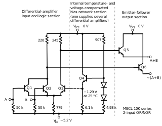
In electronics, emitter-coupled logic (ECL) is a high-speed integrated circuit bipolar transistor logic family. ECL uses an overdriven bipolar junction transistor (BJT) differential amplifier with single-ended input and limited emitter current to avoid the saturated region of operation and its slow turn-off behavior. As the current is steered between two legs of an emitter-coupled pair, ECL is sometimes called current-steering logic (CSL), current-mode logic (CML) or current-switch emitter-follower (CSEF) logic.
In information technology and computer science, a system is described as stateful if it is designed to remember preceding events or user interactions; the remembered information is called the state of the system.
In the theory of computation, a Mealy machine is a finite-state machine whose output values are determined both by its current state and the current inputs. This is in contrast to a Moore machine, whose output values are determined solely by its current state. A Mealy machine is a deterministic finite-state transducer: for each state and input, at most one transition is possible.
In digital electronics, a synchronous circuit is a digital circuit in which the changes in the state of memory elements are synchronized by a clock signal. In a sequential digital logic circuit, data are stored in memory devices called flip-flops or latches. The output of a flip-flop is constant until a pulse is applied to its "clock" input, upon which the input of the flip-flop is latched into its output. In a synchronous logic circuit, an electronic oscillator called the clock generates a string (sequence) of pulses, the "clock signal". This clock signal is applied to every storage element, so in an ideal synchronous circuit, every change in the logical levels of its storage components is simultaneous. Ideally, the input to each storage element has reached its final value before the next clock occurs, so the behaviour of the whole circuit can be predicted exactly. Practically, some delay is required for each logical operation, resulting in a maximum speed limitations at which each synchronous system can run.
Asynchronous circuit is a sequential digital logic circuit that does not use a global clock circuit or signal generator to synchronize its components. Instead, the components are driven by a handshaking circuit which indicates a completion of a set of instructions. Handshaking works by simple data transfer protocols. Many synchronous circuits were developed in early 1950s as part of bigger asynchronous systems. Asynchronous circuits and theory surrounding is a part of several steps in integrated circuit design, a field of digital electronics engineering.
In digital electronics, a tri-state or three-state buffer is a type of digital buffer that has three stable states: a high output state, a low output state, and a high-impedance state. In the high-impedance state, the output of the buffer is disconnected from the output bus, allowing other devices to drive the bus without interference from the tri-state buffer. This can be useful in situations where multiple devices are connected to the same bus and need to take turns accessing it. Systems implementing three-state logic on their bus are known as a three-state bus or tri-state bus.

In electronics, metastability is the ability of a digital electronic system to persist for an unbounded time in an unstable equilibrium or metastable state. In digital logic circuits, a digital signal is required to be within certain voltage or current limits to represent a '0' or '1' logic level for correct circuit operation; if the signal is within a forbidden intermediate range it may cause faulty behavior in logic gates the signal is applied to. In metastable states, the circuit may be unable to settle into a stable '0' or '1' logic level within the time required for proper circuit operation. As a result, the circuit can act in unpredictable ways, and may lead to a system failure, sometimes referred to as a "glitch". Metastability is an instance of the Buridan's ass paradox.
In computer architecture, clock gating is a popular power management technique used in many synchronous circuits for reducing dynamic power dissipation, by removing the clock signal when the circuit is not in use or ignores clock signal. Clock gating saves power by pruning the clock tree, at the cost of adding more logic to a circuit. Pruning the clock disables portions of the circuitry so that the flip-flops in them do not have to switch states. Switching states consumes power. When not being switched, the switching power consumption goes to zero, and only leakage currents are incurred.
Fan-in is the number of inputs a logic gate can handle. For instance the fan-in for the AND gate shown in the figure is 3. Physical logic gates with a large fan-in tend to be slower than those with a small fan-in. This is because the complexity of the input circuitry increases the input capacitance of the device. Using logic gates with higher fan-in will help in reducing the depth of a logic circuit; this is because circuit design is realized by the target logic family at a digital level, meaning any large fan-in logic gates are simply the smaller fan-in gates chained together in series at a given depth to widen the circuit instead.
In integrated circuit design, dynamic logic is a design methodology in combinational logic circuits, particularly those implemented in metal–oxide–semiconductor (MOS) technology. It is distinguished from the so-called static logic by exploiting temporary storage of information in stray and gate capacitances. It was popular in the 1970s and has seen a recent resurgence in the design of high-speed digital electronics, particularly central processing units (CPUs). Dynamic logic circuits are usually faster than static counterparts and require less surface area, but are more difficult to design. Dynamic logic has a higher average rate of voltage transitions than static logic, but the capacitive loads being transitioned are smaller so the overall power consumption of dynamic logic may be higher or lower depending on various tradeoffs. When referring to a particular logic family, the dynamic adjective usually suffices to distinguish the design methodology, e.g. dynamic CMOS or dynamic SOI design.
The ESPRESSO logic minimizer is a computer program using heuristic and specific algorithms for efficiently reducing the complexity of digital logic gate circuits. ESPRESSO-I was originally developed at IBM by Robert K. Brayton et al. in 1982. and improved as ESPRESSO-II in 1984. Richard L. Rudell later published the variant ESPRESSO-MV in 1986 and ESPRESSO-EXACT in 1987. Espresso has inspired many derivatives.
In electronics, pass transistor logic (PTL) describes several logic families used in the design of integrated circuits. It reduces the count of transistors used to make different logic gates, by eliminating redundant transistors. Transistors are used as switches to pass logic levels between nodes of a circuit, instead of as switches connected directly to supply voltages. This reduces the number of active devices, but has the disadvantage that the difference of the voltage between high and low logic levels decreases at each stage. Each transistor in series is less saturated at its output than at its input. If several devices are chained in series in a logic path, a conventionally constructed gate may be required to restore the signal voltage to the full value. By contrast, conventional CMOS logic switches transistors so the output connects to one of the power supply rails, so logic voltage levels in a sequential chain do not decrease. Simulation of circuits may be required to ensure adequate performance.

In electronics, flip-flops and latches are circuits that have two stable states that can store state information – a bistable multivibrator. The circuit can be made to change state by signals applied to one or more control inputs and will output its state. It is the basic storage element in sequential logic. Flip-flops and latches are fundamental building blocks of digital electronics systems used in computers, communications, and many other types of systems.