Backbone network

Last updated
A diagram of a nationwide network backbone. NSFNET-backbone-T3.png
A diagram of a nationwide network backbone.

A backbone or core network is a part of a computer network which interconnects networks, providing a path for the exchange of information between different LANs or subnetworks. [1] A backbone can tie together diverse networks in the same building, in different buildings in a campus environment, or over wide areas. Normally, the backbone's capacity is greater than the networks connected to it. [2]

Contents

A large corporation that has many locations may have a backbone network that ties all of the locations together, for example, if a server cluster needs to be accessed by different departments of a company that are located at different geographical locations. The pieces of the network connections (for example: Ethernet, wireless) that bring these departments together is often mentioned as network backbone. Network congestion is often taken into consideration while designing backbones. [3] [4]

One example of a backbone network is the Internet backbone. [5]

History

The theory, design principles, and first instantiation of the backbone network came from the telephone core network when traffic was purely voice. The core network was the central part of a telecommunications network that provided various services to customers who were connected by the access network. One of the main functions was to route telephone calls across the PSTN.

Typically the term referred to the high capacity communication facilities that connect primary nodes. A core network provided paths for the exchange of information between different sub-networks.

In the United States, local exchange core networks were linked by several competing interexchange networks; in the rest of the world, the core network has been extended to national boundaries.

Core networks usually had a mesh topology that provided any-to-any connections among devices on the network. Many main service providers would have their own core/backbone networks that are interconnected. Some large enterprises have their own core/backbone network, which are typically connected to the public networks.

Backbone networks create links that allow long-distance transmission, usually 10 to 100 miles, and in certain cases - up to 150 miles. This makes backbone network essential to providing long-haul wireless solutions to provide internet service, especially to remote areas. [6]

Functions

Core networks typically provided the following functionality:

  1. Aggregation: The highest level of aggregation in a service provider network. The next level in the hierarchy under the core nodes is the distribution networks and then the edge networks. Customer-premises equipment (CPE) do not normally connect to the core networks of a large service provider.
  2. Authentication: The function to decide whether the user requesting a service from the telecom network is authorized to do so within this network or not.
  3. Call Control/Switching: call control or switching functionality decides the future course of call based on the call signalling processing. E.g. switching functionality may decide based on the "called number" that the call be routed towards a subscriber within this operator's network or with number portability more prevalent to another operator's network.
  4. Charging: This functionality of the collation and processing of charging data generated by various network nodes. Two common types of charging mechanisms found in present-day networks are prepaid charging and postpaid charging. See Automatic Message Accounting
  5. Service Invocation: Core network performs the task of service invocation for its subscribers. Service invocation may happen based on some explicit action (e.g. call transfer) by user or implicitly (call waiting). It's important to note however that service "execution" may or may not be a core network functionality as third party network/nodes may take part in actual service execution.
  6. Gateways: Gateways shall be present in the core network to access other networks. Gateway functionality is dependent on the type of network it interfaces with.

Physically, one or more of these logical functionalities may simultaneously exist in a given core network node.

Besides above-mentioned functionalities, the following also formed part of a telecommunications core network:

Distributed backbone

A distributed backbone is a backbone network that consists of a number of connectivity devices connected to a series of central connectivity devices, such as hubs, switches, or routers, in a hierarchy. [7] This kind of topology allows for simple expansion and limited capital outlay for growth, because more layers of devices can be added to existing layers. [7] In a distributed backbone network, all of the devices that access the backbone share the transmission media, as every device connected to this network is sent all transmissions placed on that network. [8]

Distributed backbones, in all practicality, are in use by all large-scale networks. [9] Applications in enterprise-wide scenarios confined to a single building are also practical, as certain connectivity devices can be assigned to certain floors or departments. [7] Each floor or department possesses a LAN and a wiring closet with that workgroup's main hub or router connected to a bus-style network using backbone cabling. [10] Another advantage of using a distributed backbone is the ability for network administrator to segregate workgroups for ease of management. [7]

There is the possibility of single points of failure, referring to connectivity devices high in the series hierarchy. [7] The distributed backbone must be designed to separate network traffic circulating on each individual LAN from the backbone network traffic by using access devices such as routers and bridges. [11]

Collapsed backbone

A conventional backbone network spans distance to provide interconnectivity across multiple locations. In most cases, the backbones are the links while the switching or routing functions are done by the equipment at each location. It is a distributed architecture.

A collapsed backbone (also known as inverted backbone or backbone-in-a-box) is a type of backbone network architecture. In the case of a collapsed backbone, each location features a link back to a central location to be connected to the collapsed backbone. The collapsed backbone can be a cluster or a single switch or router. The topology and architecture of a collapsed backbone is a star or a rooted tree.

The main advantages of the collapsed backbone approach are

  1. ease of management since the backbone is in a single location and in a single box, and
  2. since the backbone is essentially the back plane or internal switching matrix of the box, proprietary, high performance technology can be used.

However, the drawback of the collapsed backbone is that if the box housing the backbone is down or there are reachability problem to the central location, the entire network will crash. These problems can be minimized by having redundant backbone boxes as well as having secondary/backup backbone locations.

Parallel backbone

There are a few different types of backbones that are used for an enterprise-wide network. When organizations are looking for a very strong and trustworthy backbone they should choose a parallel backbone. This backbone is a variation of a collapsed backbone in that it uses a central node (connection point). Although, with a parallel backbone, it allows for duplicate connections when there is more than one router or switch. Each switch and router are connected by two cables. By having more than one cable connecting each device, it ensures network connectivity to any area of the enterprise-wide network. [12]

Parallel backbones are more expensive than other backbone networks because they require more cabling than the other network topologies. Although this can be a major factor when deciding which enterprise-wide topology to use, the expense of it makes up for the efficiency it creates by adding increased performance and fault tolerance. Most organizations use parallel backbones when there are critical devices on the network. For example, if there is important data, such as payroll, that should be accessed at all times by multiple departments, then your organization should choose to implement a Parallel Backbone to make sure that the connectivity is never lost. [12]

Serial backbone

A serial backbone is the simplest kind of backbone network. [13] Serial backbones consist of two or more internet working devices connected to each other by a single cable in a daisy-chain fashion. A daisy chain is a group of connectivity devices linked together in a serial fashion. Hubs are often connected in this way to extend a network. However, hubs are not the only device that can be connected in a serial backbone. Gateways, routers, switches and bridges more commonly form part of the backbone. [14] The serial backbone topology could be used for enterprise-wide networks, though it is rarely implemented for that purpose. [15]

See also

Related Research Articles

<span class="mw-page-title-main">Router (computing)</span> Device that forwards data packets between computer networks

A router is a computer and networking device that forwards data packets between computer networks, including internetworks such as the global Internet.

<span class="mw-page-title-main">Wireless LAN</span> Computer network that links devices using wireless communication within a limited area

A wireless LAN (WLAN) is a wireless computer network that links two or more devices using wireless communication to form a local area network (LAN) within a limited area such as a home, school, computer laboratory, campus, or office building. This gives users the ability to move around within the area and remain connected to the network. Through a gateway, a WLAN can also provide a connection to the wider Internet.

A network switch is networking hardware that connects devices on a computer network by using packet switching to receive and forward data to the destination device.

In telecommunications, a customer-premises equipment or customer-provided equipment (CPE) is any terminal and associated equipment located at a subscriber's premises and connected with a carrier's telecommunication circuit at the demarcation point ("demarc"). The demarc is a point established in a building or complex to separate customer equipment from the equipment located in either the distribution infrastructure or central office of the communications service provider.

<span class="mw-page-title-main">Network topology</span> Arrangement of a communication network

Network topology is the arrangement of the elements of a communication network. Network topology can be used to define or describe the arrangement of various types of telecommunication networks, including command and control radio networks, industrial fieldbusses and computer networks.

<span class="mw-page-title-main">KNX</span> Standard in building automation

KNX is an open standard for commercial and residential building automation. KNX devices can manage lighting, blinds and shutters, HVAC, security systems, energy management, audio video, white goods, displays, remote control, etc. KNX evolved from three earlier standards; the European Home Systems Protocol (EHS), BatiBUS, and the European Installation Bus.

<span class="mw-page-title-main">Internet access</span> Individual connection to the Internet

Internet access is a facility or service that provides connectivity for a computer, a computer network, or other network device to the Internet, and for individuals or organizations to access or use applications such as email and the World Wide Web. Internet access is offered for sale by an international hierarchy of Internet service providers (ISPs) using various networking technologies. At the retail level, many organizations, including municipal entities, also provide cost-free access to the general public.

<span class="mw-page-title-main">Wireless mesh network</span> Radio nodes organized in a mesh topology

A wireless mesh network (WMN) is a communications network made up of radio nodes organized in a mesh topology. It can also be a form of wireless ad hoc network.

<span class="mw-page-title-main">Mesh networking</span> Network with multiple links between nodes

A mesh network is a local area network topology in which the infrastructure nodes connect directly, dynamically and non-hierarchically to as many other nodes as possible and cooperate with one another to efficiently route data to and from clients.

In telecommunications networks, a node is either a redistribution point or a communication endpoint.

The IP Multimedia Subsystem or IP Multimedia Core Network Subsystem (IMS) is a standardised architectural framework for delivering IP multimedia services. Historically, mobile phones have provided voice call services over a circuit-switched-style network, rather than strictly over an IP packet-switched network. Various voice over IP technologies are available on smartphones; IMS provides a standard protocol across vendors.

<span class="mw-page-title-main">Terminal server</span> Device that interfaces serial hosts to a network

A terminal server connects devices with a serial port to a local area network (LAN). Products marketed as terminal servers can be very simple devices that do not offer any security functionality, such as data encryption and user authentication. The primary application scenario is to enable serial devices to access network server applications, or vice versa, where security of the data on the LAN is not generally an issue. There are also many terminal servers on the market that have highly advanced security functionality to ensure that only qualified personnel can access various servers and that any data that is transmitted across the LAN, or over the Internet, is encrypted. Usually, companies that need a terminal server with these advanced functions want to remotely control, monitor, diagnose and troubleshoot equipment over a telecommunications network.

Switched fabric or switching fabric is a network topology in which network nodes interconnect via one or more network switches. Because a switched fabric network spreads network traffic across multiple physical links, it yields higher total throughput than broadcast networks, such as the early 10BASE5 version of Ethernet and most wireless networks such as Wi-Fi.

<span class="mw-page-title-main">Metro Ethernet</span> Metropolitan area network based on Ethernet standards

A metropolitan-area Ethernet, Ethernet MAN, carrier Ethernet or metro Ethernet network is a metropolitan area network (MAN) that is based on Ethernet standards. It is commonly used to connect subscribers to a larger service network or for internet access. Businesses can also use metropolitan-area Ethernet to connect their own offices to each other.

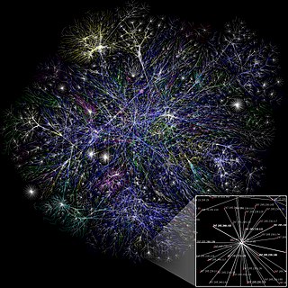
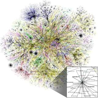
A computer network diagram is a schematic depicting the nodes and connections amongst nodes in a computer network or, more generally, any telecommunications network. Computer network diagrams form an important part of network documentation.

<span class="mw-page-title-main">Computer network</span> Network that allows computers to share resources and communicate with each other

A computer network is a set of computers sharing resources located on or provided by network nodes. Computers use common communication protocols over digital interconnections to communicate with each other. These interconnections are made up of telecommunication network technologies based on physically wired, optical, and wireless radio-frequency methods that may be arranged in a variety of network topologies.

In a hierarchical telecommunications network, the backhaul portion of the network comprises the intermediate links between the core network, or backbone network, and the small subnetworks at the edge of the network.

<span class="mw-page-title-main">EMMAN</span>

EMMAN was a company limited by guarantee and jointly owned by its members, eight Higher Education Institutions in the East Midlands region of the United Kingdom.

Avaya Unified Communications Management in Computer Networking is the name of a collection of GUI software programs from Avaya. It uses a service-oriented architecture (SOA) that serves as a foundation forunifying the configuration and monitoring of Avaya Unified Communications Servers and data systems.

IEEE 802.1aq is an amendment to the IEEE 802.1Q networking standard which adds support for Shortest Path Bridging (SPB). This technology is intended to simplify the creation and configuration of Ethernet networks while enabling multipath routing.

References

  1. "What is a Backbone?". Whatis.com. Archived from the original on May 16, 2008. Retrieved June 25, 2007.
  2. "Backbone Networks". Chapter 8. Angelfire. Archived from the original on 28 July 2020. Retrieved 2 October 2013.
  3. Turner, Brough (12 September 2007). "Congestion in the Backbone: Telecom and Internet Solutions". CircleID. Archived from the original on 18 February 2020. Retrieved 2 October 2013.
  4. Kashyap, Abhishek; Sun, Fangting; Shayman, Mark. "Relay Placement for Minimizing Congestion in Wireless Backbone Networks" (PDF). Department of Electrical and Computer Engineering, University of Maryland. Archived (PDF) from the original on 5 October 2013. Retrieved 2 October 2013.
  5. Howdie, Ben (28 January 2013). "The Backbone's connected to the…". KashFlow. Archived from the original on 5 October 2013. Retrieved 2 October 2013.
  6. Networks, Ceragon. "What is 5G Wireless Backhaul". www.ceragon.com. Archived from the original on 2022-05-20. Retrieved 2022-05-09.
  7. 1 2 3 4 5 Dean, Tamara (2010). Network+ Guide to Networks 5th Edition. Boston, MA: Cengage Course Technology. p. 202. ISBN   978-1423902454.
  8. "Distributed backbone network". BICSI Lan Design Manual (PDF). 1996. p. 20. Archived (PDF) from the original on July 19, 2011. Retrieved May 7, 2011.
  9. Dooley, Kevin (January 1, 2002). "Designing Large-Scale Networks". O'Reilly Online Catalog. p. 23. Archived from the original on November 7, 2012. Retrieved May 7, 2011.
  10. "Distributed Backbone". Archived from the original on October 9, 2011. Retrieved May 7, 2011.
  11. Boon & Kepekci (1996). BICSI Lan Design Manual. Tampa, FL. pp. 20–21.{{cite book}}: CS1 maint: location missing publisher (link)
  12. 1 2 Dean, Tamara (2010). Network+ Guide to Networks 5th Edition. Boston, MA: Cengage Course Technology. pp. 203–204. ISBN   978-1423902454.
  13. CompTIA Network+ In depth, Chapter 5 p. 169
  14. Dean, Tamara (2010). Network+ Guide to Networks 5th Edition. Boston, MA: Cengage Course Technology. ISBN   978-1423902454.
  15. "Backbone Networks". Archived from the original on 2006-07-18.