
Eurocard is an IEEE standard format for printed circuit board (PCB) cards that can be plugged together into a standard chassis which, in turn, can be mounted in a 19-inch rack. The chassis consists of a series of slotted card guides on the top and bottom, into which the cards are slid so they stand on end, like books on a shelf. At the spine of each card is one or more connectors which plug into mating connectors on a backplane that closes the rear of the chassis.

A motherboard is the main printed circuit board (PCB) in general-purpose computers and other expandable systems. It holds and allows communication between many of the crucial electronic components of a system, such as the central processing unit (CPU) and memory, and provides connectors for other peripherals. Unlike a backplane, a motherboard usually contains significant sub-systems, such as the central processor, the chipset's input/output and memory controllers, interface connectors, and other components integrated for general use.

The VESA Local Bus is a short-lived expansion bus introduced during the i486 generation of x86 IBM-compatible personal computers. Created by VESA, the VESA Local Bus worked alongside the then-dominant ISA bus to provide a standardized high-speed conduit intended primarily to accelerate video (graphics) operations. VLB provides a standardized fast path that add-in (video) card makers could tap for greatly accelerated memory-mapped I/O and DMA, while still using the familiar ISA bus to handle basic device duties such as interrupts and port-mapped I/O. Some high-end 386DX motherboards also had a VL-Bus slot.

In computing, an expansion card is a printed circuit board that can be inserted into an electrical connector, or expansion slot on a computer's motherboard to add functionality to a computer system. Sometimes the design of the computer's case and motherboard involves placing most of these slots onto a separate, removable card. Typically such cards are referred to as a riser card in part because they project upward from the board and allow expansion cards to be placed above and parallel to the motherboard.

A single-board computer (SBC) is a complete computer built on a single circuit board, with microprocessor(s), memory, input/output (I/O) and other features required of a functional computer. Single-board computers are commonly made as demonstration or development systems, for educational systems, or for use as embedded computer controllers. Many types of home computers or portable computers integrate all their functions onto a single printed circuit board.

An edge connector is the portion of a printed circuit board (PCB) consisting of traces leading to the edge of the board that are intended to plug into a matching socket. The edge connector is a money-saving device because it only requires a single discrete female connector, and they also tend to be fairly robust and durable. They are commonly used in computers for expansion slots for peripheral cards, such as PCI, PCI Express, and AGP cards.

CompactPCI is a computer bus interconnect for industrial computers, combining a Eurocard-type connector and PCI signaling and protocols. Boards are standardized to 3U or 6U sizes, and are typically interconnected via a passive backplane. The connector pin assignments are standardized by the PICMG US and PICMG Europe organizations. The connectors and the electrical rules allow for eight boards in a PCI segment. Multiple bus segments are allowed with bridges.
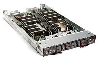
A blade server is a stripped-down server computer with a modular design optimized to minimize the use of physical space and energy. Blade servers have many components removed to save space, minimize power consumption and other considerations, while still having all the functional components to be considered a computer. Unlike a rack-mount server, a blade server fits inside a blade enclosure, which can hold multiple blade servers, providing services such as power, cooling, networking, various interconnects and management. Together, blades and the blade enclosure form a blade system, which may itself be rack-mounted. Different blade providers have differing principles regarding what to include in the blade itself, and in the blade system as a whole.

PC/104 is a family of embedded computer standards which define both form factors and computer buses by the PC/104 Consortium. Its name derives from the 104 pins on the interboard connector (ISA) in the original PC/104 specification and has been retained in subsequent revisions, despite changes to connectors. PC/104 is intended for specialized environments where a small, rugged computer system is required. The standard is modular, and allows consumers to stack together boards from a variety of COTS manufacturers to produce a customized embedded system.
Advanced Telecommunications Computing Architecture is the largest specification effort in the history of the PCI Industrial Computer Manufacturers Group (PICMG), with more than 100 companies participating. Known as AdvancedTCA, the official specification designation PICMG 3.x was ratified by the PICMG organization in December 2002. AdvancedTCA is targeted primarily to requirements for "carrier grade" communications equipment, but has recently expanded its reach into more ruggedized applications geared toward the military/aerospace industries as well. This series of specifications incorporates the latest trends in high speed interconnect technologies, next-generation processors, and improved Reliability, Availability and Serviceability (RAS).
Advanced Mezzanine Cards are printed circuit boards (PCBs) that follow a specification of the PCI Industrial Computers Manufacturers Group (PICMG). Known as AdvancedMC or AMC, the official specification designation is AMC.x. Originally AMC was targeted to requirements for carrier grade communications equipment, but later used in other markets.
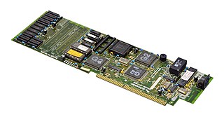
In electronic systems a diagnostic board is a specialized device with diagnostic circuitry on a printed circuit board that connects to a computer or other electronic equipment replacing an existing module, or plugging into an expansion card slot.
A CPU card is a printed circuit board (PCB) that contains the central processing unit (CPU) of a computer. CPU cards are specified by CPU clock frequency and bus type as well as other features and applications built into the card.
In computing, the motherboard form factor is the specification of a motherboard – the dimensions, power supply type, location of mounting holes, number of ports on the back panel, etc. Specifically, in the IBM PC compatible industry, standard form factors ensure that parts are interchangeable across competing vendors and generations of technology, while in enterprise computing, form factors ensure that server modules fit into existing rackmount systems. Traditionally, the most significant specification is for that of the motherboard, which generally dictates the overall size of the case. Small form factors have been developed and implemented.
CompactPCI PlusIO is an extension to the PICMG 2.0 CompactPCI industrial standard for modular computer systems. CompactPCI PlusIO was officially adopted by the PCI Industrial Computer Manufacturers Group PICMG as PICMG 2.30 CompactPCI PlusIO in November 2009. Being 100% compatible with CompactPCI, PICMG 2.30 defines a migration path to the future CompactPCI Serial standard. It defines a fixed rear I/O pin assignment that focuses on modern, fast serial point-to-point connections. The new technology succeeding parallel CompactPCI comprises both CompactPCI Serial and CompactPCI PlusIO.
CompactPCI Serial is an industrial standard for modular computer systems. It is based on the established PICMG 2.0 CompactPCI standard, which uses the parallel PCI bus for communication among a system's card components. In contrast to this, CompactPCI Serial uses only serial point-to-point connections. CompactPCI Serial was officially adopted by the PCI Industrial Computer Manufacturers Group PICMG as PICMG CPCI-S.0 CompactPCI Serial in March 2011. Its mechanical concept is based on the proven standards of IEEE 1101-1-1998 and IEEE 1101-10-1996. CompactPCI Serial includes different connectors that permit very high data rates. The new technology standard succeeding parallel CompactPCI comprises another specification called PICMG 2.30 CompactPCI PlusIO. This is why CompactPCI Serial and CompactPCI PlusIO as a whole were also called CompactPCI Plus. PICMG's first working title of CompactPCI Serial was CPLUS.0. CompactPCI Serial backplanes and chassis are developed by Schroff, Elmа, and Pixus Technologies companies, as for the CompactPCI Serial board level electronics – they are developed by MEN Mikro Elektronik, Fastwel, EKF, Emerson Embedded Computing, ADLINK, Data Patterns and Kontron.
PICMG 1.0 is a PICMG specification that defines a CPU form factor and corresponding backplane connectors for PCI-ISA passive backplanes. This standard moves components typically located on the motherboard to a single plug-in card. PICMG 1.0 CPU Cards look much like standard ISA cards with extra gold finger connections for the ISA bus and the root PCI bus. The "motherboard" is replaced with a simple "passive backplane" that has only PCI and ISA connectors attached to it. These backplane connections include a dedicated system slot of the PICMG 1.0 CPU and various connections for standard ISA and PCI peripheral cards. This backplane is simple and robust, with a very low likelihood of failure, given its passive nature. This allows a much lower Mean Time to Repair than classic computer motherboard approaches, as electronics associated with CPUs can be replaced without having to remove peripheral devices.

PICMG 1.3 is a PICMG specification which is commonly referred to as SHB Express. SHB Express is a modernization of PICMG 1.0 single-board computer specification. SHB Express, or System Host Board – Express, uses the same physical form factor as PICMG 1.0 boards. The board-to-backplane interfaces are PCI Express instead of PCI and ISA, although the use of PCI remains as an option.
PICOe (PICO Express) within computer hardware is a computer form factor in which a half sized card slot Single Board Computer (SBC) is inserted into a gold fingers card slot of a passive or active backplane. Expansion peripherals of the computer system are connected to other slots of the backplane.

Modular crate electronics are a general type of electronics and support infrastructure commonly used for trigger electronics and data acquisition in particle detectors. These types of electronics are common in such detectors because all the electronic pathways are made by discrete physical cables connecting together logic blocks on the fronts of modules. This allows circuits to be designed, built, tested, and deployed very quickly as an experiment is being put together. Then the modules can all be removed and used again when the experiment is done.


