Linear filters process time-varying input signals to produce output signals, subject to the constraint of linearity. In most cases these linear filters are also time invariant in which case they can be analyzed exactly using LTI system theory revealing their transfer functions in the frequency domain and their impulse responses in the time domain. Real-time implementations of such linear signal processing filters in the time domain are inevitably causal, an additional constraint on their transfer functions. An analog electronic circuit consisting only of linear components will necessarily fall in this category, as will comparable mechanical systems or digital signal processing systems containing only linear elements. Since linear time-invariant filters can be completely characterized by their response to sinusoids of different frequencies, they are sometimes known as frequency filters.
In engineering, a transfer function of a system, sub-system, or component is a mathematical function that models the system's output for each possible input. It is widely used in electronic engineering tools like circuit simulators and control systems. In simple cases, this function can be represented as a two-dimensional graph of an independent scalar input versus the dependent scalar output. Transfer functions for components are used to design and analyze systems assembled from components, particularly using the block diagram technique, in electronics and control theory.
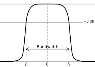
In physics and electrical engineering, a cutoff frequency, corner frequency, or break frequency is a boundary in a system's frequency response at which energy flowing through the system begins to be reduced rather than passing through.
Double-sideband suppressed-carrier transmission (DSB-SC) is transmission in which frequencies produced by amplitude modulation (AM) are symmetrically spaced above and below the carrier frequency and the carrier level is reduced to the lowest practical level, ideally being completely suppressed.
A low-pass filter is a filter that passes signals with a frequency lower than a selected cutoff frequency and attenuates signals with frequencies higher than the cutoff frequency. The exact frequency response of the filter depends on the filter design. The filter is sometimes called a high-cut filter, or treble-cut filter in audio applications. A low-pass filter is the complement of a high-pass filter.

A high-pass filter (HPF) is an electronic filter that passes signals with a frequency higher than a certain cutoff frequency and attenuates signals with frequencies lower than the cutoff frequency. The amount of attenuation for each frequency depends on the filter design. A high-pass filter is usually modeled as a linear time-invariant system. It is sometimes called a low-cut filter or bass-cut filter in the context of audio engineering. High-pass filters have many uses, such as blocking DC from circuitry sensitive to non-zero average voltages or radio frequency devices. They can also be used in conjunction with a low-pass filter to produce a band-pass filter.
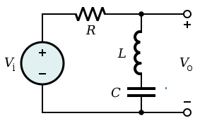
A resistor–capacitor circuit, or RC filter or RC network, is an electric circuit composed of resistors and capacitors. It may be driven by a voltage or current source and these will produce different responses. A first order RC circuit is composed of one resistor and one capacitor and is the simplest type of RC circuit.
A sine wave, sinusoidal wave, or sinusoid is a periodic wave whose waveform (shape) is the trigonometric sine function. In mechanics, as a linear motion over time, this is simple harmonic motion; as rotation, it corresponds to uniform circular motion. Sine waves occur often in physics, including wind waves, sound waves, and light waves, such as monochromatic radiation. In engineering, signal processing, and mathematics, Fourier analysis decomposes general functions into a sum of sine waves of various frequencies, relative phases, and magnitudes.
Chebyshev filters are analog or digital filters that have a steeper roll-off than Butterworth filters, and have either passband ripple or stopband ripple. Chebyshev filters have the property that they minimize the error between the idealized and the actual filter characteristic over the operating frequency range of the filter, but they achieve this with ripples in the passband. This type of filter is named after Pafnuty Chebyshev because its mathematical characteristics are derived from Chebyshev polynomials. Type I Chebyshev filters are usually referred to as "Chebyshev filters", while type II filters are usually called "inverse Chebyshev filters". Because of the passband ripple inherent in Chebyshev filters, filters with a smoother response in the passband but a more irregular response in the stopband are preferred for certain applications.
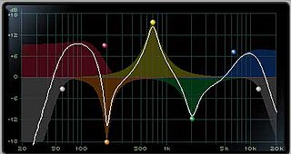
An audio filter is a frequency dependent circuit, working in the audio frequency range, 0 Hz to 20 kHz. Audio filters can amplify (boost), pass or attenuate (cut) some frequency ranges. Many types of filters exist for different audio applications including hi-fi stereo systems, musical synthesizers, effects units, sound reinforcement systems, instrument amplifiers and virtual reality systems.
The Sallen–Key topology is an electronic filter topology used to implement second-order active filters that is particularly valued for its simplicity. It is a degenerate form of a voltage-controlled voltage-source (VCVS) filter topology. It was introduced by R. P. Sallen and E. L. Key of MIT Lincoln Laboratory in 1955.

The Butterworth filter is a type of signal processing filter designed to have a frequency response that is as flat as possible in the passband. It is also referred to as a maximally flat magnitude filter. It was first described in 1930 by the British engineer and physicist Stephen Butterworth in his paper entitled "On the Theory of Filter Amplifiers".
An elliptic filter is a signal processing filter with equalized ripple (equiripple) behavior in both the passband and the stopband. The amount of ripple in each band is independently adjustable, and no other filter of equal order can have a faster transition in gain between the passband and the stopband, for the given values of ripple. Alternatively, one may give up the ability to adjust independently the passband and stopband ripple, and instead design a filter which is maximally insensitive to component variations.
An all-pass filter is a signal processing filter that passes all frequencies equally in gain, but changes the phase relationship among various frequencies. Most types of filter reduce the amplitude of the signal applied to it for some values of frequency, whereas the all-pass filter allows all frequencies through without changes in level.

Electronic filter topology defines electronic filter circuits without taking note of the values of the components used but only the manner in which those components are connected.

Zobel networks are a type of filter section based on the image-impedance design principle. They are named after Otto Zobel of Bell Labs, who published a much-referenced paper on image filters in 1923. The distinguishing feature of Zobel networks is that the input impedance is fixed in the design independently of the transfer function. This characteristic is achieved at the expense of a much higher component count compared to other types of filter sections. The impedance would normally be specified to be constant and purely resistive. For this reason, Zobel networks are also known as constant resistance networks. However, any impedance achievable with discrete components is possible.
m-derived filters or m-type filters are a type of electronic filter designed using the image method. They were invented by Otto Zobel in the early 1920s. This filter type was originally intended for use with telephone multiplexing and was an improvement on the existing constant k type filter. The main problem being addressed was the need to achieve a better match of the filter into the terminating impedances. In general, all filters designed by the image method fail to give an exact match, but the m-type filter is a big improvement with suitable choice of the parameter m. The m-type filter section has a further advantage in that there is a rapid transition from the cut-off frequency of the passband to a pole of attenuation just inside the stopband. Despite these advantages, there is a drawback with m-type filters; at frequencies past the pole of attenuation, the response starts to rise again, and m-types have poor stopband rejection. For this reason, filters designed using m-type sections are often designed as composite filters with a mixture of k-type and m-type sections and different values of m at different points to get the optimum performance from both types.
mm'-type filters, also called double-m-derived filters, are a type of electronic filter designed using the image method. They were patented by Otto Zobel in 1932. Like the m-type filter from which it is derived, the mm'-type filter type was intended to provide an improved impedance match into the filter termination impedances and originally arose in connection with telephone frequency division multiplexing. The filter has a similar transfer function to the m-type, having the same advantage of rapid cut-off, but the input impedance remains much more nearly constant if suitable parameters are chosen. In fact, the cut-off performance is better for the mm'-type if like-for-like impedance matching are compared rather than like-for-like transfer function. It also has the same drawback of a rising response in the stopband as the m-type. However, its main disadvantage is its much increased complexity which is the chief reason its use never became widespread. It was only ever intended to be used as the end sections of composite filters, the rest of the filter being made up of other sections such as k-type and m-type sections.
In signal processing, a filter is a device or process that removes some unwanted components or features from a signal. Filtering is a class of signal processing, the defining feature of filters being the complete or partial suppression of some aspect of the signal. Most often, this means removing some frequencies or frequency bands. However, filters do not exclusively act in the frequency domain; especially in the field of image processing many other targets for filtering exist. Correlations can be removed for certain frequency components and not for others without having to act in the frequency domain. Filters are widely used in electronics and telecommunication, in radio, television, audio recording, radar, control systems, music synthesis, image processing, computer graphics, and structural dynamics.
Staggered tuning is a technique used in the design of multi-stage tuned amplifiers whereby each stage is tuned to a slightly different frequency. In comparison to synchronous tuning it produces a wider bandwidth at the expense of reduced gain. It also produces a sharper transition from the passband to the stopband. Both staggered tuning and synchronous tuning circuits are easier to tune and manufacture than many other filter types.