Boundary representation

Last updated
Corsica Coachworks example generated using the B-Rep model. Notice that the surface areas are stitched together. WEAZER0.jpg
Corsica Coachworks example generated using the B-Rep model. Notice that the surface areas are stitched together.

In solid modeling and computer-aided design, boundary representation (often abbreviated B-rep or BREP) is a method for representing a 3D shape [1] by defining the limits of its volume. A solid is represented as a collection of connected surface elements, which define the boundary between interior and exterior points.

Contents

Overview

A boundary representation of a model comprises topological components (faces, edges and vertices) and the connections between them, along with geometric definitions for those components (surfaces, curves and points, respectively). A face is a bounded portion of a surface; an edge is a bounded piece of a curve and a vertex lies at a point. Other elements are the shell (a set of connected faces), the loop (a circuit of edges bounding a face) and loop-edge links (also known as winged edge links or half-edges) which are used to create the edge circuits. [2]

Compared to constructive solid geometry

Compared to the constructive solid geometry (CSG) representation, which uses only primitive objects and Boolean operations to combine them, boundary representation is more flexible and has a much richer operation set. In addition to the Boolean operations, B-rep has extrusion (or sweeping), chamfer, blending, drafting, shelling, tweaking and other operations which make use of these.

History

The basic method for BREP was developed independently in the early 1970s by both Ian C. Braid in Cambridge (for CAD) and Bruce G. Baumgart at Stanford (for computer vision). Braid continued his work with the research solid modeller BUILD which was the forerunner of many research and commercial solid modelling systems. Braid worked on the commercial systems ROMULUS, the forerunner of Parasolid, and on ACIS. Parasolid and ACIS are the basis for many of today's commercial CAD systems.

Following Braid's work for solids, a Swedish team led by Professor Torsten Kjellberg, developed the philosophy and methods for working with hybrid models, wire-frames, sheet objects and volumetric models during the early 1980s. In Finland, Martti Mäntylä produced a solid modelling system called GWB. In the USA Eastman and Weiler were also working on Boundary Representation and in Japan Professor Fumihiko Kimura and his team at Tokyo University also produced their own B-rep modelling system.

Initially CSG was used by several commercial systems because it was easier to implement. The advent of reliable commercial B-rep kernel systems like Parasolid and ACIS, mentioned above, as well as OpenCASCADE and C3D that were later developed, has led to widespread adoption of B-rep for CAD.

Boundary representation is essentially a local representation connecting faces, edges and vertices. An extension of this was to group sub-elements of the shape into logical units called geometric features, or simply features. Pioneering work was done by Kyprianou in Cambridge also using the BUILD system and continued and extended by Jared and others. Features are the basis of many other developments, allowing high-level "geometric reasoning" about shape for comparison, process-planning, manufacturing, etc.

Boundary representation has also been extended to allow special, non-solid model types called non-manifold models. As described by Braid, normal solids found in nature have the property that, at every point on the boundary, a small enough sphere around the point is divided into two pieces, one inside and one outside the object.[ citation needed ] [3] Non-manifold models break this rule. An important sub-class of non-manifold models are sheet objects which are used to represent thin-plate objects and integrate surface modelling into a solid modelling environment.

Standardization

Standardization for boundary representation took time to develop. In a meeting organized by the Computer-Aided Manufacturing International (CAM-I) in 1979 the IGES format was discussed for solid model transfer. IGES was not, then, suitable. Another complication was the coexistence of, then, two major representations, CSG and Boundary Representation, although use of CSG in commercial systems started to decline later. Further developments within CAM-I led to the Experimental Boundary Format, known as XBF, which was proposed to IGES as a possibility for extension to cover Boundary Representation models. However, this was not taken up. Towards the end of the 1980s a project called CAD*I developed a standard representation which then became one of the bases for the development of the STEP solid model format, the first widely accepted data exchange format for Boundary Representation.

In the world of data-exchange, STEP, the Standard for the Exchange of Product Model data also defines some data models for boundary representations in a neutral form which can be mapped to specific data structures. The common generic topological and geometric models are defined in ISO 10303-42 Geometric and topological representation. The following Application Integrated Resources (AICs) define boundary models that are constraints of the generic geometric and topological capabilities:

See also

Related Research Articles

<span class="mw-page-title-main">Computer-aided design</span> Constructing a product by means of computer

Computer-aided design (CAD) is the use of computers to aid in the creation, modification, analysis, or optimization of a design. This software is used to increase the productivity of the designer, improve the quality of design, improve communications through documentation, and to create a database for manufacturing. Designs made through CAD software help protect products and inventions when used in patent applications. CAD output is often in the form of electronic files for print, machining, or other manufacturing operations. The terms computer-aided drafting (CAD) and computer-aided design and drafting (CADD) are also used.

<span class="mw-page-title-main">ACIS</span> Geometric modeling kernel developed by Spatial Corporation

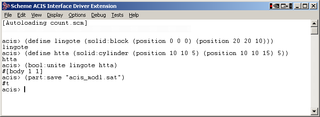
The 3D ACIS Modeler (ACIS) is a geometric modeling kernel developed by Spatial Corporation, part of Dassault Systemes. ACIS is used by many software developers in industries such as computer-aided design (CAD), computer-aided manufacturing (CAM), computer-aided engineering (CAE), architecture, engineering and construction (AEC), coordinate-measuring machine (CMM), 3D animation, and shipbuilding. ACIS provides software developers and manufacturers the underlying 3D modeling functionality.

<span class="mw-page-title-main">Geometric primitive</span> Basic shapes represented in vector graphics

In vector computer graphics, CAD systems, and geographic information systems, geometric primitive is the simplest geometric shape that the system can handle. Sometimes the subroutines that draw the corresponding objects are called "geometric primitives" as well. The most "primitive" primitives are point and straight line segment, which were all that early vector graphics systems had.

<span class="mw-page-title-main">Constructive solid geometry</span> Creating a complex 3D surface or object by combining primitive objects

Constructive solid geometry is a technique used in solid modeling. Constructive solid geometry allows a modeler to create a complex surface or object by using Boolean operators to combine simpler objects, potentially generating visually complex objects by combining a few primitive ones.

<span class="mw-page-title-main">Solid modeling</span> Set of principles for modeling solid geometry

Solid modeling is a consistent set of principles for mathematical and computer modeling of three-dimensional shapes (solids). Solid modeling is distinguished within the broader related areas of geometric modeling and computer graphics, such as 3D modeling, by its emphasis on physical fidelity. Together, the principles of geometric and solid modeling form the foundation of 3D-computer-aided design and in general support the creation, exchange, visualization, animation, interrogation, and annotation of digital models of physical objects.

<span class="mw-page-title-main">Geometric dimensioning and tolerancing</span> System for defining and representing engineering tolerances

Geometric dimensioning and tolerancing (GD&T) is a system for defining and communicating engineering tolerances via a symbolic language on engineering drawings and computer-generated 3D models that describes a physical object's nominal geometry and the permissible variation thereof. GD&T is used to define the nominal geometry of parts and assemblies, the allowable variation in size, form, orientation, and location of individual features, and how features may vary in relation to one another such that a component is considered satisfactory for its intended use. Dimensional specifications define the nominal, as-modeled or as-intended geometry, while tolerance specifications define the allowable physical variation of individual features of a part or assembly.

<span class="mw-page-title-main">IGES</span> Initial Graphics Exchange Specification

The Initial Graphics Exchange Specification (IGES) is a vendor-neutral file format that allows the digital exchange of information among computer-aided design (CAD) systems. It is an ASCII-based textual format.

STEP-file is a widely used data exchange form of STEP. ISO 10303 can represent 3D objects in computer-aided design (CAD) and related information. Due to its ASCII structure, a STEP-file is easy to read, with typically one instance per line. The format of a STEP-file is defined in ISO 10303-21 Clear Text Encoding of the Exchange Structure.

<span class="mw-page-title-main">Freeform surface modelling</span> Techniques for creating complex surfaces in 3D graphics software

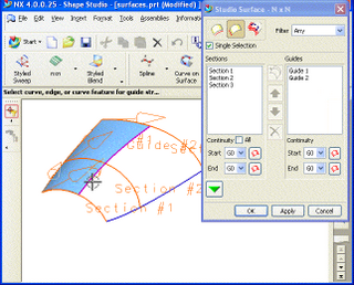
Freeform surface modelling is a technique for engineering freeform surfaces with a CAD or CAID system.

Product and manufacturing information, also abbreviated PMI, conveys non-geometric attributes in 3D computer-aided design (CAD) and Collaborative Product Development systems necessary for manufacturing product components and assemblies. PMI may include geometric dimensions and tolerances, 3D annotation (text) and dimensions, surface finish, and material specifications. PMI is used in conjunction with the 3D model within model-based definition to allow for the elimination of 2D drawings for data set utilization.

JT is an openly-published ISO-standardized 3D CAD data exchange format used for product visualization, collaboration, digital mockups, and other purposes. It was developed by Siemens.

CAD data exchange is a method of drawing data exchange used to translate between different computer-aided design (CAD) authoring systems or between CAD and other downstream CAx systems.

<span class="mw-page-title-main">Rhinoceros 3D</span> 3D computer graphics software

Rhinoceros is a commercial 3D computer graphics and computer-aided design (CAD) application software that was developed by TLM, Inc, dba Robert McNeel & Associates, an American, privately held, and employee-owned company that was founded in 1978. Rhinoceros geometry is based on the NURBS mathematical model, which focuses on producing mathematically precise representation of curves and freeform surfaces in computer graphics.

<span class="mw-page-title-main">Cobalt (CAD program)</span> 3D computer graphics software

Cobalt is a parametric-based computer-aided design (CAD) and 3D modeling program that runs on both Macintosh and Microsoft Windows operating systems. The program combines the direct-modeling way to create and edit objects and the highly structured, history-driven parametric way exemplified by programs like Pro/ENGINEER. A product of Ashlar-Vellum, Cobalt is Wireframe-based and history-driven with associativity and 2D equation-driven parametrics and constraints. It offers surfacing tools, mold design tools, detailing, and engineering features. Cobalt includes a library of 149,000 mechanical parts.

PartXplore is a computer aided design (CAD) file viewer developed by Sescoi for reading, analyzing, and sharing 3D and 2D CAD files. It was introduced in 2008 and is supported from local Vero offices. The software is available as a viewer and an evaluation version.

<span class="mw-page-title-main">Digital Geometric Kernel</span>

Digital Geometric Kernel, is a software development framework and a set of components for enabling 3D/CAD functionality in Windows applications, developed by DInsight.

Solid Modeling Solutions is a software company that specializes in 3D geometry software.

<span class="mw-page-title-main">C3D Toolkit</span> Geometric modelling kernel

C3D Toolkit is a proprietary cross-platform geometric modeling kit software developed by Russian by C3D Labs. It's written in C++. It can be licensed by other companies for use in their 3D computer graphics software products. The most widely known software in which C3D Toolkit is typically used are computer aided design (CAD), computer-aided manufacturing (CAM), and computer-aided engineering (CAE) systems.

<span class="mw-page-title-main">Onshape</span> Computer-aided design software system

Onshape is a computer-aided design (CAD) software system, delivered over the Internet via a software as a service (SAAS) model. It makes extensive use of cloud computing, with compute-intensive processing and rendering performed on Internet-based servers, and users are able to interact with the system via a web browser or the iOS and Android apps. As a SAAS system, Onshape upgrades are released directly to the web interface, and the software does not require maintenance work from the user.

References

  1. https://3d.bk.tudelft.nl/courses/backup/geo1004/2020/data/handout1.2.pdf
  2. "What Is Boundary Representation (B-Rep) | C Graphics | Programmerbay". 2019-09-14. Retrieved 2024-05-04.
  3. Pernot, Jean-Philippe (23 January 2015). "Automatic reconstruction of 3D partitions from exported non-manifold models". Proceedings of IDMME - Virtual Concept 2010 Bordeaux, France, October 20 – 22, 2010.

Further reading