Cable television headend

Last updated

Dish antennas for the South Brooklyn headend of Charter Communications (formerly Time Warner Cable) Toroidheadendjeh.JPG
Dish antennas for the South Brooklyn headend of Charter Communications (formerly Time Warner Cable)

A cable television headend is a master facility for receiving television signals for processing and distribution over a cable television system. A headend facility may be staffed or unstaffed and is typically surrounded by some type of security fencing. The building is typically sturdy and purpose-built to provide security, cooling, and easy access for the electronic equipment used to receive and re-transmit video over the local cable infrastructure. One can also find head ends in power-line communication (PLC) substations and Internet communications networks.

Contents

Reception

Nearly all cable TV systems carry subscription content that is relayed from a satellite in geosynchronous orbit. Encrypted to prevent unauthorized use, this content is uplinked from one or more earth stations operated by various content delivery companies. The content is then analog or digitally modulated and transmitted through the cable network (the OSP or "OutSide Plant") to subscriber homes by means of coaxial or fiber-optic cables buried underground or strung from utility poles.

Most cable TV systems also carry local over-the-air television stations for distribution. While each terrestrial channel represents a defined frequency, one or more commercial-grade receiving television antennas are used to receive the multiple channels that the cable company wishes to distribute. These antennas are often built into a single tower structure called a master antenna television structure. Commercial TV pre-amplifiers strengthen the weakened terrestrial TV signals for distribution, usually after re-modulation using a cable-specific analog or digital scheme.

Some cable TV systems receive the local television stations' programming by dedicated coaxial cable, microwave link or fiber-optic line, installed between the local station and the headend. A device called a modulator at the local station's facilities feed their programming over this line to the cable TV headend, which in turn receives it with another device called a demodulator. It is then distributed through the cable TV headend to subscribers. This is usually more reliable than receiving the local stations' broadcasts over the air with an antenna. However, off-air reception is used as a backup by the headend in case of failure. In some cases systems receive local channels by satellite.

Other sources of programming include those delivered via fiber optics, telephone wires, the Internet, microwave towers and local public-access television channels that are sent to the cable headend on an upstream frequency over the cable system itself (known in the industry as "T"-channels), or via a dedicated line set up by the cable company, as mentioned earlier for reception of local television stations' programming by the headend.

Signal processing

A standard rack-mount headend Headend-rack.jpg
A standard rack-mount headend

Once a television signal is received, it must be processed. For digital satellite TV signals, a dedicated commercial satellite receiver is needed for each channel that is to be distributed by the cable system; these are usually rack-mountable receivers that are designed to take up less space than consumer receivers. They output video and stereo audio signals as well as a digital signal for digital plants.

Analog terrestrial TV signals require a processor which is a RF receiver that outputs video and audio. In some cases the processor will include a built-in modulator.

Digital terrestrial TV signals require a special digital processor.

Digital channels are usually received on an L band QAM stream from a satellite, which uses multiplexing. Using special receivers such as the Motorola MPS, the signal can be demultiplexed or "Demuxed" to extract specific channels from the multiplexed signal. At this point, local insertion may be performed to add content specifically targeted to the local geographic area.

Analog Modulation

Agile channel modulator Cable headend modulator.jpg
Agile channel modulator

Cable television signals are then mixed in accordance with the cable system's channel numbering scheme using a series of cable modulators (one for each channel), which is in turn fed into a frequency multiplexer or signal combiner. The mixed signals are sent into a broadband amplifier, then sent into the cable system by the trunk line and continuously re-amplified as needed.

Modulators essentially take an input signal and attach it to a specific frequency. For example, in North America, NTSC standards dictate that CH2 is a 6 MHz wide channel with its luminance carrier at 55.25 MHz, so the modulator for channel 2 will impose the appropriate input signal on to the 55.25 MHz frequency to be received by any TV tuned to Channel 2.

Digital Modulation

Digital channels are modulated as well; however, instead of each channel being modulated on to a specific frequency, multiple digital channels are modulated on to one specific ATSC frequency. Using QAM (Quadrature Amplitude Modulation), a CATV operator can place usually up to eight subchannels on each channel so channel 2 may actually be carrying channels 1–8 in a viewer's city. Set-top boxes (STBs) or CableCards are required to receive these digital signals and are provided by the cable operator themselves.

Many modern cable systems are now "all digital" meaning analog video signals have been discontinued in order to reuse spectrum. The RF channels analog used to occupy are now open for a cable system to reuse most commonly as High Speed Data (commonly referred to in the industry as "HSD") channels to increase subscriber download/upload internet speeds. (see DOCSIS) Analog video removal also essentially eliminates cable theft since analog signals were transmitted unencrypted. Most digital video signals are compressed to MPEG-2 and MPEG-4 formats in order to combine multiple video streams into a QAM making the most efficient use of spectrum which a customer cable set top box receives, demodulates, de-encrypts and displays as a virtual channel number that the viewer recognizes. In many cases the same TV network may appear multiple times in a local channel lineup as a different channel the viewer sees (I.E. CNN as 34, 334, 1034) this is due to previous generations of channel lineups kept in service and intended to not confuse viewers who are familiar with the network appearing on a number they are used to. Although a channel may be in a line up multiple times the RF QAM it is combined or "muxed" into is modulated and compressed just once. A set top box tunes to that same QAM when any instance of that network is called by the viewer. Virtual channeling also allows the cable operator to change the physical frequency a QAM is on without the viewer noticing the channel number changing in their lineup.

Most digital cable systems encrypt their signals (both data and video) to eliminate unauthorized reception.

National Video Transporting

Super Headend

Most commonly in large nationwide cable systems a central or "super headend" is in service to feed a local hub via a fiber optic transport circuit. In some cases a single super headend could service a cable company's entire service footprint. Super headends allow for a single site of satellite dishes that can be placed in optimal locations for satellite coverage and signal strength, usually in areas of high ground elevation and open terrain. In large cable systems, a provider may operate multiple super headends as a way of redundancy in the event of a failure. Super headends also create a cost-effective environment for cable operators as the amount of equipment and faculties is greatly reduced and the signals can be replicated and transmitted to local hubs that feed a community or city.

Market Center Headend

In some large nationwide cable systems, a sort of median point between a large super headend and local hub exists and is known as a market center headend or region headend. Typically a market center headend receives its national video content from the super headend, then forwards that alongside local ad splicing and local channels to local hubs. Market center headends are regularly staffed while hubs are not (outside of normal maintenance and servicing). A main benefit of a market center headend is it can give more attention to local service and details than a nationwide super headend could. For example, a market center headend allows for engineers to pull local video feeds such as public access channels and local channels for viewing and analyzation of video quality defects when such an issue may not be immediately noticed locally. Another benefit is the quick action of channel blackouts in certain areas during times of carriage contract disputes with broadcasters. Market center headends can service hubs in a large city, an entire state or even multiple states.

Cable Hubs and Nodes

A cable hub is a building or shelter usually smaller than a headend that takes an already processed video signal from a headend and transmits it to a local community. (or multiple communities) Most cable hubs are used in conjunction with an HFC Plant. Combined IP video and data enters a hub via a microwave or fiber optic transport circuit and gets routed to QAM devices such as a cable modem termination system which changes the IP data into an RF QAM to be combined with other services (such as video on demand, switched video) and transmitted to the subscriber. The RF from each service gets combined in the hub to ultimately a single coax cable broken down per node, but right before it leaves the hub to feed customers, gets changed to fiber optic light to feed local cable nodes which may cover a large building, a neighborhood or in rural areas, an entire community. The cable node located in the field in-turn reverses the optical light from the hub and changes the signals back to RF over coaxial cable. This is called a "forward" path (download). The inverse happens on the upload or "return" path as customers transmit data back to a hub. Cable nodes were initially intended to reduce amplifier cascade and improve signal quality to subscribers distant from a hub. Modern cable nodes still serve the same purpose for amplifier cascade reduction, but now are strategically placed in areas of high data density to better allocate bandwidth availability and reduce oversubscribing in a particular area. Cable nodes also allow for multiple channel lineups or public access markets out of the same hub.

Local Channel Receiving

Since a super headend feeding a hub may be located out of market, a hub may also be equipped with an antenna tower and off-air antennas to receive the local channels in that particular market. The local channels received at that hub then get distributed to other hubs in the area. Depending on its geographic footprint and location, a hub may also receive local channels from neighbouring markets and combine them with the immediate market giving viewers from that particular hub multi-market programming, which the cable company may black out certain programming per carriage contract and FCC regulations. A cable system may build a fibre optic circuit as a primary path to a local television station as an additional mean to bring its programming into a cable system and utilise the off-air antennas as a backup.

OTN Hub

OTN (Optical Terminal Node) hubs are usually a remote site spawning from a larger hub, located in and intended to serve rural communities and are equipped with just HFC combining equipment for a limited number of optical nodes in the community. An OTN's primary purpose is to extend the HFC cable plant to rural communities without having to locate on site, core network equipment such as a CMTS or video edge QAM devices. The OTN relies on the parent hub (where the core network equipment is actually located) to provide the video and HSD services to its area. An OTN is commonly a small shelter or building containing just a few equipment racks.

Transporting Services to an OTN

Since core network equipment (CMTS, video edge devices, core router/switches) are not located within the OTN itself, HSD and video services are multiplexed and transmitted to the OTN from the parent hub over an RF-to-fiber link. At the OTN, the individual services get de-multiplexed and connected into the OTN's forward/return combining plant for distribution to the community. OTNs also allow rual communities to be served with the same tier of service urban communities can receive without the cable operator having to invest large amounts of money on additional fiber construction and networking equipment for only a limited number of potential customers.

See also

Related Research Articles

<span class="mw-page-title-main">Cable television</span> Television content transmitted via signals on coaxial cable

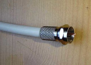
Cable television is a system of delivering television programming to consumers via radio frequency (RF) signals transmitted through coaxial cables, or in more recent systems, light pulses through fibre-optic cables. This contrasts with broadcast television, in which the television signal is transmitted over-the-air by radio waves and received by a television antenna attached to the television; or satellite television, in which the television signal is transmitted over-the-air by radio waves from a communications satellite orbiting the Earth, and received by a satellite dish antenna on the roof. FM radio programming, high-speed Internet, telephone services, and similar non-television services may also be provided through these cables. Analog television was standard in the 20th century, but since the 2000s, cable systems have been upgraded to digital cable operation.

In electronics and telecommunications, modulation is the process of varying one or more properties of a periodic waveform, called the carrier signal, with a separate signal called the modulation signal that typically contains information to be transmitted. For example, the modulation signal might be an audio signal representing sound from a microphone, a video signal representing moving images from a video camera, or a digital signal representing a sequence of binary digits, a bitstream from a computer.

A communications system or communication system is a collection of individual telecommunications networks systems, relay stations, tributary stations, and terminal equipment usually capable of interconnection and interoperation to form an integrated whole. The components of a communications system serve a common purpose, are technically compatible, use common procedures, respond to controls, and operate in union.

<span class="mw-page-title-main">Repeater</span> Relay station

In telecommunications, a repeater is an electronic device that receives a signal and retransmits it. Repeaters are used to extend transmissions so that the signal can cover longer distances or be received on the other side of an obstruction. Some types of repeaters broadcast an identical signal, but alter its method of transmission, for example, on another frequency or baud rate.

<span class="mw-page-title-main">RF modulator</span> Device which converts video signals to the format used by over-the-air RF broadcasts

An RF modulator is an electronic device used to convert signals from devices such as media players, VCRs and game consoles to a format that can be handled by a device designed to receive a modulated RF input, such as a radio or television receiver. Its input is a baseband signal, which is used to modulate a radio frequency source.

<span class="mw-page-title-main">Frequency-division multiplexing</span> Signal processing technique in telecommunications

In telecommunications, frequency-division multiplexing (FDM) is a technique by which the total bandwidth available in a communication medium is divided into a series of non-overlapping frequency bands, each of which is used to carry a separate signal. This allows a single transmission medium such as a microwave radio link, cable or optical fiber to be shared by multiple independent signals. Another use is to carry separate serial bits or segments of a higher rate signal in parallel.

Digital Video Broadcasting - Cable (DVB-C) is the DVB European consortium standard for the broadcast transmission of digital television over cable. This system transmits an MPEG-2 or MPEG-4 family digital audio/digital video stream, using a QAM modulation with channel coding. The standard was first published by the ETSI in 1994, and subsequently became the most widely used transmission system for digital cable television in Europe, Asia and South America. It is deployed worldwide in systems ranging from the larger cable television networks (CATV) down to smaller satellite master antenna TV (SMATV) systems.

Digital cable is the distribution of cable television using digital data and video compression. The technology was first developed by General Instrument. By 2000, most cable companies offered digital features, eventually replacing their previous analog-based cable by the mid 2010s. During the late 2000s, broadcast television converted to the digital HDTV standard, which was incompatible with existing analog cable systems.

Hybrid fiber-coaxial (HFC) is a broadband telecommunications network that combines optical fiber and coaxial cable. It has been commonly employed globally by cable television operators since the early 1990s.

<span class="mw-page-title-main">Tuner (radio)</span> Frequency selection subsystem for various receiver systems

A tuner is a subsystem that receives radio frequency (RF) transmissions, such as FM broadcasting, and converts the selected carrier frequency and its associated bandwidth into a fixed frequency that is suitable for further processing, usually because a lower frequency is used on the output. Broadcast FM/AM transmissions usually feed this intermediate frequency (IF) directly into a demodulator that converts the radio signal into audio-frequency signals that can be fed into an amplifier to drive a loudspeaker.

<span class="mw-page-title-main">Cable modem termination system</span> Equipment used to provide high speed data services

A cable modem termination system is a piece of equipment, typically located in a cable company's headend or hubsite, which is used to provide data services, such as cable Internet or Voice over IP, to cable subscribers. A CMTS provides many of the same functions provided by the DSLAM in a DSL system.

<span class="mw-page-title-main">ATSC tuner</span> Tuner for digital television channels

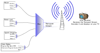
An ATSCtuner, often called an ATSC receiver or HDTV tuner, is a type of television tuner that allows reception of digital television (DTV) television channels that use ATSC standards, as transmitted by television stations in North America, parts of Central America, and South Korea. Such tuners are usually integrated into a television set, VCR, digital video recorder (DVR), or set-top box which provides audio/video output connectors of various types.

<span class="mw-page-title-main">Digital television adapter</span> Type of television tuner to display digital signals on analog sets

A digital television adapter (DTA), commonly known as a converter box or decoder box, is a television tuner that receives a digital television (DTV) transmission, and converts the digital signal into an analog signal that can be received and displayed on an analog television set. Some also have an HDMI output since some TVs with HDMI do not have a digital tuner. The input digital signal may be over-the-air terrestrial television signals received by a television antenna, or signals from a digital cable system. It normally does not refer to satellite TV, which has always required a set-top box either to operate the big satellite dish, or to be the integrated receiver/decoder (IRD) in the case of direct-broadcast satellites (DBS).

Analog transmission is a transmission method of conveying information using a continuous signal which varies in amplitude, phase, or some other property in proportion to that information. It could be the transfer of an analog signal, using an analog modulation method such as frequency modulation (FM) or amplitude modulation (AM), or no modulation at all.

<span class="mw-page-title-main">Switched video</span>

Switched video or switched digital video (SDV), sometimes referred to as switched broadcast (SWB), is a telecommunications industry term for a network scheme for distributing digital video via a cable. Switched video sends the digital video more efficiently freeing bandwidth. The scheme applies to digital video distribution both on typical cable TV systems using QAM channels, or on IPTV systems.

<span class="mw-page-title-main">Cable converter box</span> Converting cable television channels to analogue signal

A cable converter box or television converter box is an electronic tuning device that transposes/converts channels from a cable television service to an analog RF signal on a single channel, usually VHF channel 3 or 4, or to a different output for digital televisions such as HDMI.

Radio over fiber (RoF) or RF over fiber (RFoF) refers to a technology whereby light is modulated by a radio frequency signal and transmitted over an optical fiber link. Main technical advantages of using fiber optical links are lower transmission losses and reduced sensitivity to noise and electromagnetic interference compared to all-electrical signal transmission.

Zenith Cable Modem was one of the first proprietary cable modems. The two basic models are one operating at 500 kilobits per second (kbit/s), and the other at four megabits per second (Mbit/s) with BPSK and approximately a 25% alpha.

Hotel television systems are the in-suite television content presented in hotel-rooms, other hotel environments and in the hospitality industry for in-room entertainment, as well as hospitals, assisted living, senior care and nursing homes. These services may be free for the guest or paid, depending on the service and the individual hotel's or hotel chain’s policy. Generally these services are controlled by using the remote control.

In telecommunications, radio frequency over glass (RFoG) is a deep-fiber network design in which the coax portion of the hybrid fiber coax (HFC) network is replaced by a single-fiber passive optical network (PON). Downstream and return-path transmission use different wavelengths to share the same fiber. The return-path wavelength standard is expected to be 1610 nm, but early deployments have used 1590 nm. Using 1590/1610 nm for the return path allows the fiber infrastructure to support both RFoG and a standards-based PON simultaneously, operating with 1490 nm downstream and 1310 nm return-path wavelengths.

References