Quadrature amplitude modulation

Last updated

Quadrature amplitude modulation (QAM) is the name of a family of digital modulation methods and a related family of analog modulation methods widely used in modern telecommunications to transmit information. It conveys two analog message signals, or two digital bit streams, by changing (modulating) the amplitudes of two carrier waves, using the amplitude-shift keying (ASK) digital modulation scheme or amplitude modulation (AM) analog modulation scheme. The two carrier waves are of the same frequency and are out of phase with each other by 90°, a condition known as orthogonality or quadrature. The transmitted signal is created by adding the two carrier waves together. At the receiver, the two waves can be coherently separated (demodulated) because of their orthogonality. Another key property is that the modulations are low-frequency/low-bandwidth waveforms compared to the carrier frequency, which is known as the narrowband assumption.

Contents

Phase modulation (analog PM) and phase-shift keying (digital PSK) can be regarded as a special case of QAM, where the amplitude of the transmitted signal is a constant, but its phase varies. This can also be extended to frequency modulation (FM) and frequency-shift keying (FSK), for these can be regarded as a special case of phase modulation.

QAM is used extensively as a modulation scheme for digital telecommunication systems, such as in 802.11 Wi-Fi standards. Arbitrarily high spectral efficiencies can be achieved with QAM by setting a suitable constellation size, limited only by the noise level and linearity of the communications channel. [1]   QAM is being used in optical fiber systems as bit rates increase; QAM16 and QAM64 can be optically emulated with a three-path interferometer. [2] [3]

Demodulation

Analog QAM: PAL color bar signal on a Vectorscope PAL Vector.png
Analog QAM: PAL color bar signal on a Vectorscope

In a QAM signal, one carrier lags the other by 90°, and its amplitude modulation is customarily referred to as the in-phase component, denoted by I(t). The other modulating function is the quadrature component, Q(t). So the composite waveform is mathematically modeled as:

  or:


(Eq.1)

where fc is the carrier frequency.  At the receiver, a coherent demodulator multiplies the received signal separately with both a cosine and sine signal to produce the received estimates of I(t) and Q(t). For example:

Using standard trigonometric identities, we can write this as:

Low-pass filtering r(t) removes the high frequency terms (containing fct), leaving only the I(t) term. This filtered signal is unaffected by Q(t), showing that the in-phase component can be received independently of the quadrature component.  Similarly, we can multiply sc(t) by a sine wave and then low-pass filter to extract Q(t).

The graphs of the sine (solid red) and cosine (dotted blue) functions are sinusoids of different phases. Sine and Cosine.svg
The graphs of the sine (solid red) and cosine (dotted blue) functions are sinusoids of different phases.

The addition of two sinusoids is a linear operation that creates no new frequency components. So the bandwidth of the composite signal is comparable to the bandwidth of the DSB (double-sideband) components. Effectively, the spectral redundancy of DSB enables a doubling of the information capacity using this technique. This comes at the expense of demodulation complexity. In particular, a DSB signal has zero-crossings at a regular frequency, which makes it easy to recover the phase of the carrier sinusoid. It is said to be self-clocking. But the sender and receiver of a quadrature-modulated signal must share a clock or otherwise send a clock signal. If the clock phases drift apart, the demodulated I and Q signals bleed into each other, yielding crosstalk. In this context, the clock signal is called a "phase reference". Clock synchronization is typically achieved by transmitting a burst subcarrier or a pilot signal. The phase reference for NTSC, for example, is included within its colorburst signal.

Analog QAM is used in:

Fourier analysis

Applying Euler's formula to the sinusoids in Eq.1 , the positive-frequency portion of sc (or analytic representation) is:

where denotes the Fourier transform, and ︿I and ︿Q are the transforms of I(t) and Q(t). This result represents the sum of two DSB-SC signals with the same center frequency. The factor of i (= e/2) represents the 90° phase shift that enables their individual demodulations.

Digital QAM

Digital 16-QAM with example symbols 16-QAM Demonstration 3.gif
Digital 16-QAM with example symbols
Constellation points for 4-QAM, 16-QAM, 32-QAM, and 64-QAM overlapped Rectangular constellation for QAM.svg
Constellation points for 4-QAM, 16-QAM, 32-QAM, and 64-QAM overlapped

As in many digital modulation schemes, the constellation diagram is useful for QAM. In QAM, the constellation points are usually arranged in a square grid with equal vertical and horizontal spacing, although other configurations are possible (e.g. a hexagonal or triangular grid). In digital telecommunications the data is usually binary, so the number of points in the grid is typically a power of 2 (2, 4, 8, …), corresponding to the number of bits per symbol. The simplest and most commonly used QAM constellations consist of points arranged in a square, i.e. 16-QAM, 64-QAM and 256-QAM (even powers of two). Non-square constellations, such as Cross-QAM, can offer greater efficiency but are rarely used because of the cost of increased modem complexity.

By moving to a higher-order constellation, it is possible to transmit more bits per symbol. However, if the mean energy of the constellation is to remain the same (by way of making a fair comparison), the points must be closer together and are thus more susceptible to noise and other corruption; this results in a higher bit error rate and so higher-order QAM can deliver more data less reliably than lower-order QAM, for constant mean constellation energy. Using higher-order QAM without increasing the bit error rate requires a higher signal-to-noise ratio (SNR) by increasing signal energy, reducing noise, or both.

If data rates beyond those offered by 8-PSK are required, it is more usual to move to QAM since it achieves a greater distance between adjacent points in the I-Q plane by distributing the points more evenly. The complicating factor is that the points are no longer all the same amplitude and so the demodulator must now correctly detect both phase and amplitude, rather than just phase.

64-QAM and 256-QAM are often used in digital cable television and cable modem applications. In the United States, 64-QAM and 256-QAM are the mandated modulation schemes for digital cable (see QAM tuner) as standardised by the SCTE in the standard ANSI/SCTE 07 2013. Note that many marketing people will refer to these as QAM-64 and QAM-256.[ citation needed ] In the UK, 64-QAM is used for digital terrestrial television (Freeview) whilst 256-QAM is used for Freeview-HD.

Bit-loading (bits per QAM constellation) on an ADSL line ADSL spectrum Fritz Box Fon WLAN.png
Bit-loading (bits per QAM constellation) on an ADSL line

Communication systems designed to achieve very high levels of spectral efficiency usually employ very dense QAM constellations. For example, current Homeplug AV2 500-Mbit/s powerline Ethernet devices use 1024-QAM and 4096-QAM, [4] as well as future devices using ITU-T G.hn standard for networking over existing home wiring (coaxial cable, phone lines and power lines); 4096-QAM provides 12 bits/symbol. Another example is ADSL technology for copper twisted pairs, whose constellation size goes up to 32768-QAM (in ADSL terminology this is referred to as bit-loading, or bit per tone, 32768-QAM being equivalent to 15 bits per tone). [5]

Ultra-high capacity microwave backhaul systems also use 1024-QAM. [6] With 1024-QAM, adaptive coding and modulation (ACM) and XPIC, vendors can obtain gigabit capacity in a single 56 MHz channel. [6]

Interference and noise

In moving to a higher order QAM constellation (higher data rate and mode) in hostile RF/microwave QAM application environments, such as in broadcasting or telecommunications, multipath interference typically increases. There is a spreading of the spots in the constellation, decreasing the separation between adjacent states, making it difficult for the receiver to decode the signal appropriately. In other words, there is reduced noise immunity. There are several test parameter measurements which help determine an optimal QAM mode for a specific operating environment. The following three are most significant: [7]

See also

Related Research Articles

<span class="mw-page-title-main">Amplitude modulation</span> Radio modulation via wave amplitude

Amplitude modulation (AM) is a modulation technique used in electronic communication, most commonly for transmitting messages with a radio wave. In amplitude modulation, the amplitude of the wave is varied in proportion to that of the message signal, such as an audio signal. This technique contrasts with angle modulation, in which either the frequency of the carrier wave is varied, as in frequency modulation, or its phase, as in phase modulation.

<span class="mw-page-title-main">Frequency modulation</span> Encoding of information in a carrier wave by varying the instantaneous frequency of the wave

Frequency modulation (FM) is the encoding of information in a carrier wave by varying the instantaneous frequency of the wave. The technology is used in telecommunications, radio broadcasting, signal processing, and computing.

In electronics and telecommunications, modulation is the process of varying one or more properties of a periodic waveform, called the carrier signal, with a separate signal called the modulation signal that typically contains information to be transmitted. For example, the modulation signal might be an audio signal representing sound from a microphone, a video signal representing moving images from a video camera, or a digital signal representing a sequence of binary digits, a bitstream from a computer.

<span class="mw-page-title-main">Single-sideband modulation</span> Type of modulation

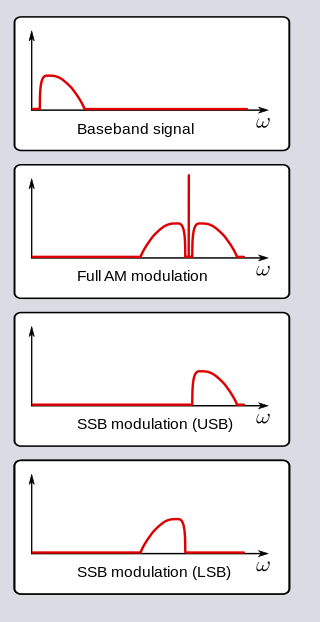
In radio communications, single-sideband modulation (SSB) or single-sideband suppressed-carrier modulation (SSB-SC) is a type of modulation used to transmit information, such as an audio signal, by radio waves. A refinement of amplitude modulation, it uses transmitter power and bandwidth more efficiently. Amplitude modulation produces an output signal the bandwidth of which is twice the maximum frequency of the original baseband signal. Single-sideband modulation avoids this bandwidth increase, and the power wasted on a carrier, at the cost of increased device complexity and more difficult tuning at the receiver.

<span class="mw-page-title-main">Baseband</span> Range of frequencies occupied by an unmodulated signal

In telecommunications and signal processing, baseband is the range of frequencies occupied by a signal that has not been modulated to higher frequencies. Baseband signals typically originate from transducers, converting some other variable into an electrical signal. For example, the electronic output of a microphone is a baseband signal that is analogous to the applied voice audio. In conventional analog radio broadcasting, the baseband audio signal is used to modulate an RF carrier signal of a much higher frequency.

Double-sideband suppressed-carrier transmission (DSB-SC) is transmission in which frequencies produced by amplitude modulation (AM) are symmetrically spaced above and below the carrier frequency and the carrier level is reduced to the lowest practical level, ideally being completely suppressed.

Phase-shift keying (PSK) is a digital modulation process which conveys data by changing (modulating) the phase of a constant frequency carrier wave. The modulation is accomplished by varying the sine and cosine inputs at a precise time. It is widely used for wireless LANs, RFID and Bluetooth communication.

Demodulation is extracting the original information-bearing signal from a carrier wave. A demodulator is an electronic circuit that is used to recover the information content from the modulated carrier wave. There are many types of modulation so there are many types of demodulators. The signal output from a demodulator may represent sound, images or binary data.

A satellite modem or satmodem is a modem used to establish data transfers using a communications satellite as a relay. A satellite modem's main function is to transform an input bitstream to a radio signal and vice versa.

<span class="mw-page-title-main">Phasor</span> Complex number representing a particular sine wave

In physics and engineering, a phasor is a complex number representing a sinusoidal function whose amplitude, and initial phase are time-invariant and whose angular frequency is fixed. It is related to a more general concept called analytic representation, which decomposes a sinusoid into the product of a complex constant and a factor depending on time and frequency. The complex constant, which depends on amplitude and phase, is known as a phasor, or complex amplitude, and sinor or even complexor.

<span class="mw-page-title-main">Lock-in amplifier</span> Type of amplifier that emphasizes a specific frequency in a noisy signal

A lock-in amplifier is a type of amplifier that can extract a signal with a known carrier wave from an extremely noisy environment. Depending on the dynamic reserve of the instrument, signals up to a million times smaller than noise components, potentially fairly close by in frequency, can still be reliably detected. It is essentially a homodyne detector followed by low-pass filter that is often adjustable in cut-off frequency and filter order.

<span class="mw-page-title-main">Constellation diagram</span> Signal representation

A constellation diagram is a representation of a signal modulated by a digital modulation scheme such as quadrature amplitude modulation or phase-shift keying. It displays the signal as a two-dimensional xy-plane scatter diagram in the complex plane at symbol sampling instants. In a manner similar to that of a phasor diagram, the angle of a point, measured counterclockwise from the horizontal axis, represents the phase shift of the carrier wave from a reference phase; the distance of a point from the origin represents a measure of the amplitude or power of the signal.

In digital modulation, minimum-shift keying (MSK) is a type of continuous-phase frequency-shift keying that was developed in the late 1950s by Collins Radio employees Melvin L. Doelz and Earl T. Heald. Similar to OQPSK, MSK is encoded with bits alternating between quadrature components, with the Q component delayed by half the symbol period.

<span class="mw-page-title-main">In-phase and quadrature components</span> Mathematical technique for manipulating signals etc.

A sinusoid with modulation can be decomposed into, or synthesized from, two amplitude-modulated sinusoids that are in quadrature phase, i.e., with a phase offset of one-quarter cycle. All three sinusoids have the same center frequency. The two amplitude-modulated sinusoids are known as the in-phase (I) and quadrature (Q) components, which describes their relationships with the amplitude- and phase-modulated carrier.

In telecommunications, the carrier-to-noise ratio, often written CNR or C/N, is the signal-to-noise ratio (SNR) of a modulated signal. The term is used to distinguish the CNR of the radio frequency passband signal from the SNR of an analog base band message signal after demodulation. For example, with FM radio, the strength of the 100 MHz carrier with modulations would be considered for CNR, whereas the audio frequency analogue message signal would be for SNR; in each case, compared to the apparent noise. If this distinction is not necessary, the term SNR is often used instead of CNR, with the same definition.

<span class="mw-page-title-main">Carrier recovery</span>

A carrier recovery system is a circuit used to estimate and compensate for frequency and phase differences between a received signal's carrier wave and the receiver's local oscillator for the purpose of coherent demodulation.

<span class="mw-page-title-main">Amplitude and phase-shift keying</span>

Amplitude and phase-shift keying (APSK) is a digital modulation scheme that conveys data by modulating both the amplitude and the phase of a carrier wave. In other words, it combines both amplitude-shift keying (ASK) and phase-shift keying (PSK). This allows for a lower bit error rate for a given modulation order and signal-to-noise ratio, at the cost of increased complexity, compared to ASK or PSK alone.

Differential phase is a kind of linearity distortion which affects the color hue in TV broadcasting.

IQ imbalance is a performance-limiting issue in the design of a class of radio receivers known as direct conversion receivers. These translate the received radio frequency signal directly from the carrier frequency to baseband using a single mixing stage.

Constellation shaping is an energy efficiency enhancement method for digital signal modulation that improves upon amplitude and phase-shift keying (APSK) and conventional quadrature amplitude modulation (QAM) by modifying the continuous uniform distribution of the data symbols to match the channel. In a channel corrupted by an additive white Gaussian noise (AWGN), this implies transmitting low-energy signals more frequently than high-energy signals with the target to approach a Gaussian distribution of the transmission power.

References

  1. "Digital Modulation Efficiencies". Barnard Microsystems. Archived from the original on 2011-04-30.
  2. "Ciena tests 200G via 16-QAM with Japan-U.S. Cable Network". lightwave. April 17, 2014. Retrieved 7 November 2016.
  3. Kylia products Archived July 13, 2011, at the Wayback Machine , dwdm mux demux, 90 degree optical hybrid, d(q) psk demodulatorssingle polarization
  4. http://www.homeplug.org/media/filer_public/a1/46/a1464318-f5df-46c5-89dc-7243d8ccfcee/homeplug_av2_whitepaper_150907.pdf Homeplug_AV2 whitepaper
  5. http://www.itu.int/rec/T-REC-G.992.3-200904-I section 8.6.3 Constellation mapper - maximum number of bits per constellation BIMAX ≤ 15
  6. 1 2 http://www.trangosys.com/products/point-to-point-wireless-backhaul/licensed-wireless/trangolink-apex-orion.shtml A Apex Orion
  7. Howard Friedenberg and Sunil Naik. "Hitless Space Diversity STL Enables IP+Audio in Narrow STL Bands" (PDF). 2005 National Association of Broadcasters Annual Convention. Archived from the original (PDF) on March 23, 2006. Retrieved April 17, 2005.

Further reading