Composite video

Last updated

Composite video baseband signal (CVBS)
Composite-video-cable.jpg
On consumer products a yellow RCA connector is typically used for composite video.
Type Analog video connector
Production history
Designed 1954 [1] –1956 [2]
General specifications
Length Maximum of 50 m[ citation needed ]
External Yes
Video signal NTSC, PAL or SECAM video
Pins 1 plus grounding shield
Connector RCA connector
Electrical
Signal1 volt [3]
Pinout
Pin 1 center video
Pin 2 sheath ground

Composite video is an baseband analog video format that typically carries a 525 or 625 line interlaced signal on a single channel, unlike the higher-quality S-Video (two channels) and the even higher-quality component video (three or more channels).

Contents

A yellow RCA connector is typically used for composite video, with the audio being carried on separate additional L/R RCA connectors. In professional settings, or on devices that are too small for an RCA connector, such as a digital camera, other types of connectors can be used.

Composite video is also known by the initials CVBS for Composite Video Baseband Signal or Color, Video, Blanking and Sync, [4] [5] or is simply referred to as SD video for the standard-definition television signal it conveys.

There are three dominant variants of composite video signals, corresponding to the analog color system used (NTSC, PAL, and SECAM), but purely monochrome signals can also be used.

Signal components

Composite video signal graphic Composite Video.svg
Composite video signal graphic
NTSC composite video signal (analog) NTSC Signal.png
NTSC composite video signal (analog)

A composite video signal combines, on one wire, the video information required to recreate a color picture, as well as line and frame synchronization pulses. The color video signal is a linear combination of the luminance () of the picture and a modulated subcarrier which carries the chrominance or color information (), a combination of hue and saturation. Details of the combining process vary between the NTSC, PAL and SECAM systems.

The frequency spectrum of the modulated color signal overlaps that of the baseband signal, and separation relies on the fact that frequency components of the baseband signal tend to be near harmonics of the horizontal scanning rate, while the color carrier is selected to be an odd multiple of half the horizontal scanning rate; this produces a modulated color signal that consists mainly of harmonic frequencies that fall between the harmonics in the baseband luma signal, rather than both being in separate continuous frequency bands alongside each other in the frequency domain. The signals may be separated using a comb filter. [6] In other words, the combination of luma and chrominance is indeed a frequency-division technique, but it is much more complex than typical frequency-division multiplexing systems like the one used to multiplex analog radio stations on both the AM and FM bands.

A gated and filtered signal derived from the color subcarrier, called the burst or colorburst, is added to the horizontal blanking interval of each line (excluding lines in the vertical sync interval) as a synchronizing signal and amplitude reference for the chrominance signals. In NTSC composite video, the 3.58 MHz burst signal is inverted in phase (180° out of phase) from the reference subcarrier. [7] In PAL, the phase of the 4.43 MHz color subcarrier alternates on successive lines. In SECAM, no colorburst is used since phase information is irrelevant.

Composite artifacts

Enlarged detail from a video source exhibiting dot crawl. Note the distinctive checkerboard pattern on the vertical edges between yellow and blue areas. Crawl.jpg
Enlarged detail from a video source exhibiting dot crawl. Note the distinctive checkerboard pattern on the vertical edges between yellow and blue areas.

The combining of component signals to form the composite signal does the same, causing a checkerboard video artifact known as dot crawl. Dot crawl is a defect that results from crosstalk due to the intermodulation of the chrominance and luminance components of the signal. This is usually seen when chrominance is transmitted with high bandwidth, and its spectrum reaches into the band of the luminance frequencies. Comb filters are commonly used to separate signals and eliminate these artifacts from composite sources. S-Video and component video avoid this problem as they maintain the component signals physically separate.

Recording

Most home analog video equipment record a signal in (roughly) composite format: LaserDiscs and [[type C videotape] for example store a true composite signal modulated, while consumer videotape formats (including VHS and Betamax) and commercial and industrial tape formats (including U-matic) use modified composite signals FM encoded (generally known as color-under). [8] The professional D-2 videocassette format digitally storing a sampled signal and losslessly reproduces composite video signals using PCM encoding of the analog signal on the magnetic tape. With the advent of affordable higher sampling speed analog to digital converters, realtime composite to YUV sampled digital sampling has been possible since the 1980s and raw waveform sampling and software decoding since the 2010s. [9]

Extensions

A number of so-called extensions to the visible TV image can be transmitted using composite video. Since TV screens hide the vertical blanking interval of a composite video signal, these take advantage of the unseen parts of the signal. Examples of extensions include teletext, closed captioning, information regarding the show title, a set of reference colors that allows TV sets to automatically correct NTSC hue maladjustments, widescreen signaling (WSS) for switching between 4:3 and 16:9 display formats, etc.

Connectors and cable

Rear of the Polish Elwro 800 Junior computer. DIN output carries a composite video signal to an external monitor. Elwro 800 Junior jednostka centralna tyl.jpg
Rear of the Polish Elwro 800 Junior computer. DIN output carries a composite video signal to an external monitor.
Intergraph Intense3D Voodoo Rush with TV-out; S-video (topmost connector) and composite video (yellow RCA connector below) IntergraphVoodooRush.jpg
Intergraph Intense3D Voodoo Rush with TV-out; S-video (topmost connector) and composite video (yellow RCA connector below)

In home applications, the composite video signal is typically connected using an RCA connector, normally yellow. It is often accompanied with red and white connectors for right and left audio channels respectively. BNC connectors and higher quality coaxial cable are often used in professional television studios and post-production applications. BNC connectors were also used for composite video connections on early home VCRs, often accompanied by either RCA connector or a 5-pin DIN connector for audio. The BNC connector, in turn, post dated the PL-259 connector featured on first-generation VCRs.

Video cables are 75 ohm impedance, low in capacitance. Typical values run from 52 pF/m for an HDPE-foamed dielectric precision video cable to 69 pF/m for a solid PE dielectric cable. [11]

Digital sampling and modern usage

The active image area of composite and s-video signals are digitally stored at 720x576i25 PAL and 720x480i29.7 (or 720x488) pixels. This does not represent the whole signal. Hardware typically samples at four times the color subcarrier frequency (4fsc) that includes the vertical blanking interval (VBI). Only commerical video capture devices used in broadcast output images with the extra VBI space. Direct sampling with high speed ADCs and software time base correction has allowed projects like the open-source CVBS-Decode [9] to create a D-2 like 4fsc stream that preserves and allows full presentation and inspection of the entire composite signal. This can then be comb-filtered or chroma-decoded to a color image on a standard computer or via DAC played back to a TV.

Composite is no longer the universal standard it once was for consumers after the digital era began phasing out analog CRT displays and virtually all consumer devices moved to using HDMI. Modified versions of composite such as 960H (960x576) are still in wide use for CCTV systems today in consumer use alongside fpv drones.[ citation needed ]

Modulators

Some devices, such as Videocassette recorders (VCR), video game consoles, and home computers output composite video. This may then be converted to FM RF with an RF modulator that generates the proper carrier (often for channel 3 or 4 in North America, channel 36 in Europe). Sometimes this modulator is built into the product (such as video game consoles, VCRs, or the Atari, Commodore 64, or TRS-80 CoCo home-computers), is an external unit powered by the computer (TI-99/4A), or with an independent power supply. [lower-alpha 1]

Because of the digital television transition most television sets no longer have analog television tuners but DVB-T and ATSC digital ones. They therefore cannot accept a signal from an analog modulator. However, composite video has an established market for both devices that convert it to channel 3/4 outputs, as well as devices that convert standards like VGA to composite, therefore it has offered opportunities to repurpose older composite monitors for newer devices.

Demodulation loss

The process of modulating RF with the original video signal, and then demodulating the original signal again in the TV, introduces losses including added noise or interference. For these reasons, it is best to use composite connections instead of RF connections if possible for live signals and sample the source FM RF signal for recorded formats. Some video equipment and modern televisions have only RF input.

See also

Notes

  1. In the United States, using an external RF modulator frees the manufacturer from obtaining FCC approval for each variation of a device. Through the early 1980s, electronics that output a television channel signal were required to meet the same shielding requirements as broadcast television equipment, thus forcing manufacturers such as Apple to omit an RF modulator, and Texas Instruments to have their RF modulator as an external unit, which they had certified by the FCC without mentioning they were planning to sell it with a computer. In Europe, while most countries used the same broadcast standard, there were different modulation standards (PAL-G versus PAL-I, for example), and using an external modulator allowed manufacturers to make a single product and easily sell it to different countries by changing the modulator.

Related Research Articles

<span class="mw-page-title-main">Analog television</span> Television that uses analog signals

Analog television is the original television technology that uses analog signals to transmit video and audio. In an analog television broadcast, the brightness, colors and sound are represented by amplitude, phase and frequency of an analog signal.

<span class="mw-page-title-main">Chrominance</span> Colour in an image or video

Chrominance is the signal used in video systems to convey the color information of the picture, separately from the accompanying luma signal. Chrominance is usually represented as two color-difference components: U = B′ − Y′ (blue − luma) and V = R′ − Y′ (red − luma). Each of these different components may have scale factors and offsets applied to it, as specified by the applicable video standard.

<span class="mw-page-title-main">NTSC</span> Analog television system

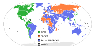
NTSC is the first American standard for analog television, published in 1941. In 1961, it was assigned the designation System M. It is also known as EIA standard 170.

<span class="mw-page-title-main">PAL</span> Colour encoding system for analogue television

Phase Alternating Line (PAL) is a colour encoding system for analog television. It was one of three major analogue colour television standards, the others being NTSC and SECAM. In most countries it was broadcast at 625 lines, 50 fields per second, and associated with CCIR analogue broadcast television systems B, D, G, H, I or K. The articles on analog broadcast television systems further describe frame rates, image resolution, and audio modulation.

<span class="mw-page-title-main">SECAM</span> French analog color television system

SECAM, also written SÉCAM, is an analog color television system that was used in France, Russia and some other countries or territories of Europe and Africa. It was one of three major analog color television standards, the others being PAL and NTSC. Like PAL, a SECAM picture is also made up of 625 interlaced lines and is displayed at a rate of 25 frames per second. However, due to the way SECAM processes color information, it is not compatible with the German PAL video format standard. This page primarily discusses the SECAM colour encoding system. The articles on broadcast television systems and analog television further describe frame rates, image resolution, and audio modulation. SECAM video is composite video because the luminance and chrominance are transmitted together as one signal.

<span class="mw-page-title-main">Video</span> Electronic moving image

Video is an electronic medium for the recording, copying, playback, broadcasting, and display of moving visual media. Video was first developed for mechanical television systems, which were quickly replaced by cathode-ray tube (CRT) systems, which, in turn, were replaced by flat-panel displays of several types.

<span class="mw-page-title-main">RF modulator</span> Device which converts video signals to the format used by over-the-air RF broadcasts

An RF modulator is an electronic device used to convert signals from devices such as media players, VCRs and game consoles to a format that can be handled by a device designed to receive a modulated RF input, such as a radio or television receiver. Its input is a baseband signal, which is used to modulate a radio frequency source.

<span class="mw-page-title-main">SCART</span> 21-pin connector for audio-visual equipment

SCART is a French-originated standard and associated 21-pin connector for connecting audio-visual (AV) equipment. The name SCART comes from Syndicat des Constructeurs d'Appareils Radiorécepteurs et Téléviseurs, "Radio and Television Receiver Manufacturers' Association", the French organisation that created the connector in the mid-1970s. The related European standard EN 50049 has then been refined and published in 1978 by CENELEC, calling it péritelevision, but it is commonly called by the abbreviation péritel in French.

<span class="mw-page-title-main">Colorburst</span> Synchronisation signal in colour video

Colorburst is an analog and composite video signal generated by a video-signal generator used to keep the chrominance subcarrier synchronized in a color television signal. By synchronizing an oscillator with the colorburst at the back porch (beginning) of each scan line, a television receiver is able to restore the suppressed carrier of the chrominance (color) signals, and in turn decode the color information. The most common use of colorburst is to genlock equipment together as a common reference with a vision mixer in a television studio using a multi-camera setup.

<span class="mw-page-title-main">RCA connector</span> Electrical connector used for analog audio and video

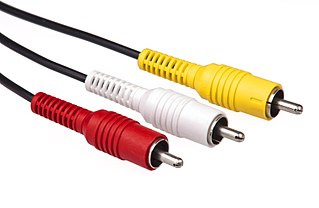
The RCA connector is a type of electrical connector commonly used to carry audio and video signals. The name RCA derives from the company Radio Corporation of America, which introduced the design in the 1930s. The connector’s male plug and female jack are called RCA plug and RCA jack.

<span class="mw-page-title-main">S-Video</span> Signal format for standard-definition video

S-Video is an analog video signal format that carries standard-definition video, typically at 525 lines or 625 lines. It encodes video luma and chrominance on two separate channels, achieving higher image quality than composite video which encodes all video information on one channel. It also eliminates several types of visual defects such as dot crawl which commonly occur with composite video. Although it improved over composite video, S-Video has lower color resolution than component video, which is encoded over three channels.

A subcarrier is a sideband of a radio frequency carrier wave, which is modulated to send additional information. Examples include the provision of colour in a black and white television system or the provision of stereo in a monophonic radio broadcast. There is no physical difference between a carrier and a subcarrier; the "sub" implies that it has been derived from a carrier, which has been amplitude modulated by a steady signal and has a constant frequency relation to it.

<span class="mw-page-title-main">Component video</span> Video signal that has been split into component channels

Component video is an analog video signal that has been split into two or more component channels. In popular use, it refers to a type of component analog video (CAV) information that is transmitted or stored as three separate signals. Component video can be contrasted with composite video in which all the video information is combined into a single signal that is used in analog television. Like composite, component cables do not carry audio and are often paired with audio cables.

In telecommunications, a pilot signal is a signal, usually a single frequency, transmitted over a communications system for supervisory, control, equalization, continuity, synchronization, or reference purposes.

<span class="mw-page-title-main">Vectorscope</span>

A Vectorscope is a special type of oscilloscope used in both audio and video applications. Whereas an oscilloscope or waveform monitor normally displays a plot of signal vs. time, a vectorscope displays an X-Y plot of two signals, which can reveal details about the relationship between these two signals. Vectorscopes are highly similar in operation to oscilloscopes operated in X-Y mode; however those used in video applications have specialized graticules, and accept standard television or video signals as input.

<span class="mw-page-title-main">Tuner (radio)</span> Frequency selection subsystem for various receiver systems

A tuner is a subsystem that receives radio frequency (RF) transmissions, such as FM broadcasting, and converts the selected carrier frequency and its associated bandwidth into a fixed frequency that is suitable for further processing, usually because a lower frequency is used on the output. Broadcast FM/AM transmissions usually feed this intermediate frequency (IF) directly into a demodulator that converts the radio signal into audio-frequency signals that can be fed into an amplifier to drive a loudspeaker.

<span class="mw-page-title-main">Composite monitor</span>

A composite monitor or composite video monitor is any analog video display that receives input in the form of an analog composite video signal to a defined specification. A composite video signal encodes all information on a single conductor; a composite cable has a single live conductor plus earth. Other equipment with display functionality includes monitors with more advanced interfaces and connectors giving a better picture, including analog VGA, and digital DVI, HDMI, and DisplayPort; and television (TV) receivers which are self-contained, receiving and displaying video RF broadcasts received with an internal tuner. Video monitors are used for displaying computer output, closed-circuit television and other applications requiring a two-dimensional monochrome or colour image.

Time base correction (TBC) is a technique to reduce or eliminate errors caused by mechanical instability present in analog recordings on mechanical media.

<span class="mw-page-title-main">Digital television adapter</span> Type of television tuner to display digital signals on analog sets

A digital television adapter (DTA), commonly known as a converter box or decoder box, is a television tuner that receives a digital television (DTV) transmission, and converts the digital signal into an analog signal that can be received and displayed on an analog television set. Some also have an HDMI output since some TVs with HDMI do not have a digital tuner. The input digital signal may be over-the-air terrestrial television signals received by a television antenna, or signals from a digital cable system. It normally does not refer to satellite TV, which has always required a set-top box either to operate the big satellite dish, or to be the integrated receiver/decoder (IRD) in the case of direct-broadcast satellites (DBS).

This glossary defines terms that are used in the document "Defining Video Quality Requirements: A Guide for Public Safety", developed by the Video Quality in Public Safety (VQIPS) Working Group. It contains terminology and explanations of concepts relevant to the video industry. The purpose of the glossary is to inform the reader of commonly used vocabulary terms in the video domain. This glossary was compiled from various industry sources.

References

  1. "Definition: composite video". computer language. Retrieved 23 May 2019.
  2. "the cable bible" . Retrieved 23 May 2019.
  3. "Understanding Analog Video Signals". Analog Devices.
  4. "TUTORIAL 734 Video Basics". Maxim Integrated. Maxim Integrated. 2002. Archived from the original on 14 July 2018. Retrieved 14 July 2018.
  5. Silva, Robert (11 September 2020). "Composite Video Connections Explained - Many home theater devices still support composite video inputs". Lifewire Tech for Humans. Lifewire.
  6. "Understanding Video Comb Filters" (PDF). Sencore Tech Tips. No. 201.
  7. SMPTE STANDARD for Television – Composite Analog Video Signal – NTSC for Studio Applications. 2004. pp. 1–21. doi:10.5594/SMPTE.ST170.2004. ISBN   978-1-61482-335-3.{{cite book}}: |journal= ignored (help)
  8. "US Patent 4323915". US Patent and Trademark Office. Archived from the original on 20 December 2016. Retrieved 12 May 2014.
  9. 1 2 Munday, Harry (2021). "CVBS-Decode - Software Defined Composite Video Decoder".{{cite web}}: CS1 maint: url-status (link)
  10. "Elwro 800 Junior - MCbx". oldcomputer.info. Archived from the original on 18 March 2017. Retrieved 5 May 2018.
  11. "LC-1 Audio Cable Design Notes". Blue Jeans Cable. Archived from the original on 28 November 2011. Retrieved 21 January 2012.