The candela is the unit of luminous intensity in the International System of Units (SI). It measures luminous power per unit solid angle emitted by a light source in a particular direction. Luminous intensity is analogous to radiant intensity, but instead of simply adding up the contributions of every wavelength of light in the source's spectrum, the contribution of each wavelength is weighted by the luminosity function, the model of the sensitivity of the human eye to different wavelengths, standardized by the CIE and ISO. A common wax candle emits light with a luminous intensity of roughly one candela. If emission in some directions is blocked by an opaque barrier, the emission would still be approximately one candela in the directions that are not obscured.
In physics, the cross section is a measure of the probability that a specific process will take place when some kind of radiant excitation intersects a localized phenomenon. For example, the Rutherford cross-section is a measure of probability that an alpha particle will be deflected by a given angle during an interaction with an atomic nucleus. Cross section is typically denoted σ (sigma) and is expressed in units of area, more specifically in barns. In a way, it can be thought of as the size of the object that the excitation must hit in order for the process to occur, but more exactly, it is a parameter of a stochastic process.

In particle physics, Rutherford scattering is the elastic scattering of charged particles by the Coulomb interaction. It is a physical phenomenon explained by Ernest Rutherford in 1911 that led to the development of the planetary Rutherford model of the atom and eventually the Bohr model. Rutherford scattering was first referred to as Coulomb scattering because it relies only upon the static electric (Coulomb) potential, and the minimum distance between particles is set entirely by this potential. The classical Rutherford scattering process of alpha particles against gold nuclei is an example of "elastic scattering" because neither the alpha particles nor the gold nuclei are internally excited. The Rutherford formula further neglects the recoil kinetic energy of the massive target nucleus.
In optics, Lambert's cosine law says that the radiant intensity or luminous intensity observed from an ideal diffusely reflecting surface or ideal diffuse radiator is directly proportional to the cosine of the angle θ between the observer's line of sight and the surface normal; I = I0 cos θ. The law is also known as the cosine emission law or Lambert's emission law. It is named after Johann Heinrich Lambert, from his Photometria, published in 1760.
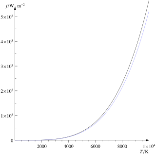
The Stefan–Boltzmann law, also known as Stefan's law, describes the intensity of the thermal radiation emitted by matter in terms of that matter's temperature. It is named for Josef Stefan, who empirically derived the relationship, and Ludwig Boltzmann who derived the law theoretically.
In geometry, a solid angle is a measure of the amount of the field of view from some particular point that a given object covers. That is, it is a measure of how large the object appears to an observer looking from that point. The point from which the object is viewed is called the apex of the solid angle, and the object is said to subtend its solid angle at that point.
An infinitesimal rotation matrix or differential rotation matrix is a matrix representing an infinitely small rotation.
In radiometry, radiance is the radiant flux emitted, reflected, transmitted or received by a given surface, per unit solid angle per unit projected area. Radiance is used to characterize diffuse emission and reflection of electromagnetic radiation, and to quantify emission of neutrinos and other particles. The SI unit of radiance is the watt per steradian per square metre. It is a directional quantity: the radiance of a surface depends on the direction from which it is being observed.

In classical electromagnetism, polarization density is the vector field that expresses the density of permanent or induced electric dipole moments in a dielectric material. When a dielectric is placed in an external electric field, its molecules gain electric dipole moment and the dielectric is said to be polarized. The electric dipole moment induced per unit volume of the dielectric material is called the electric polarization of the dielectric.

In photometry, illuminance is the total luminous flux incident on a surface, per unit area. It is a measure of how much the incident light illuminates the surface, wavelength-weighted by the luminosity function to correlate with human brightness perception. Similarly, luminous emittance is the luminous flux per unit area emitted from a surface. Luminous emittance is also known as luminous exitance.

In particle physics, the Klein–Nishina formula gives the differential cross section of photons scattered from a single free electron, calculated in the lowest order of quantum electrodynamics. It was first derived in 1928 by Oskar Klein and Yoshio Nishina, constituting one of the first successful applications of the Dirac equation. The formula describes both the Thomson scattering of low energy photons and the Compton scattering of high energy photons, showing that the total cross section and expected deflection angle decrease with increasing photon energy.
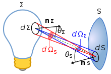
Etendue or étendue is a property of light in an optical system, which characterizes how "spread out" the light is in area and angle. It corresponds to the beam parameter product (BPP) in Gaussian beam optics. Other names for etendue include acceptance, throughput, light grasp, light-gathering power, optical extent, and the AΩ product. Throughput and AΩ product are especially used in radiometry and radiative transfer where it is related to the view factor. It is a central concept in nonimaging optics.
Radiative transfer is the physical phenomenon of energy transfer in the form of electromagnetic radiation. The propagation of radiation through a medium is affected by absorption, emission, and scattering processes. The equation of radiative transfer describes these interactions mathematically. Equations of radiative transfer have application in a wide variety of subjects including optics, astrophysics, atmospheric science, and remote sensing. Analytic solutions to the radiative transfer equation (RTE) exist for simple cases but for more realistic media, with complex multiple scattering effects, numerical methods are required. The present article is largely focused on the condition of radiative equilibrium.

In radiometry, radiant flux or radiant power is the radiant energy emitted, reflected, transmitted, or received per unit time, and spectral flux or spectral power is the radiant flux per unit frequency or wavelength, depending on whether the spectrum is taken as a function of frequency or of wavelength. The SI unit of radiant flux is the watt (W), one joule per second, while that of spectral flux in frequency is the watt per hertz and that of spectral flux in wavelength is the watt per metre —commonly the watt per nanometre.
Photon polarization is the quantum mechanical description of the classical polarized sinusoidal plane electromagnetic wave. An individual photon can be described as having right or left circular polarization, or a superposition of the two. Equivalently, a photon can be described as having horizontal or vertical linear polarization, or a superposition of the two.
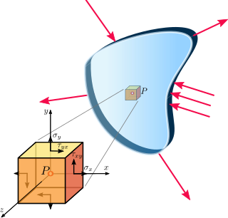
In continuum mechanics, a material is said to be under plane stress if the stress vector is zero across a particular plane. When that situation occurs over an entire element of a structure, as is often the case for thin plates, the stress analysis is considerably simplified, as the stress state can be represented by a tensor of dimension 2. A related notion, plane strain, is often applicable to very thick members.
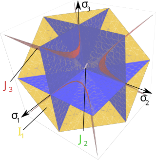
A yield surface is a five-dimensional surface in the six-dimensional space of stresses. The yield surface is usually convex and the state of stress of inside the yield surface is elastic. When the stress state lies on the surface the material is said to have reached its yield point and the material is said to have become plastic. Further deformation of the material causes the stress state to remain on the yield surface, even though the shape and size of the surface may change as the plastic deformation evolves. This is because stress states that lie outside the yield surface are non-permissible in rate-independent plasticity, though not in some models of viscoplasticity.
In fluid mechanics and mathematics, a capillary surface is a surface that represents the interface between two different fluids. As a consequence of being a surface, a capillary surface has no thickness in slight contrast with most real fluid interfaces.
In physics, and especially scattering theory, the momentum-transfer cross section is an effective scattering cross section useful for describing the average momentum transferred from a particle when it collides with a target. Essentially, it contains all the information about a scattering process necessary for calculating average momentum transfers but ignores other details about the scattering angle.

Lode coordinates or Haigh–Westergaard coordinates. are a set of tensor invariants that span the space of real, symmetric, second-order, 3-dimensional tensors and are isomorphic with respect to principal stress space. This right-handed orthogonal coordinate system is named in honor of the German scientist Dr. Walter Lode because of his seminal paper written in 1926 describing the effect of the middle principal stress on metal plasticity. Other examples of sets of tensor invariants are the set of principal stresses or the set of kinematic invariants . The Lode coordinate system can be described as a cylindrical coordinate system within principal stress space with a coincident origin and the z-axis parallel to the vector .