Camera resectioning

Last updated

Camera resectioning is the process of estimating the parameters of a pinhole camera model approximating the camera that produced a given photograph or video; it determines which incoming light ray is associated with each pixel on the resulting image. Basically, the process determines the pose of the pinhole camera.

Contents

Usually, the camera parameters are represented in a 3 × 4 projection matrix called the camera matrix . The extrinsic parameters define the camera pose (position and orientation) while the intrinsic parameters specify the camera image format (focal length, pixel size, and image origin).

This process is often called geometric camera calibration or simply camera calibration, although that term may also refer to photometric camera calibration or be restricted for the estimation of the intrinsic parameters only. Exterior orientation and interior orientation refer to the determination of only the extrinsic and intrinsic parameters, respectively.

The classic camera calibration requires special objects in the scene, which is not required in camera auto-calibration . Camera resectioning is often used in the application of stereo vision where the camera projection matrices of two cameras are used to calculate the 3D world coordinates of a point viewed by both cameras.

Formulation

The camera projection matrix is derived from the intrinsic and extrinsic parameters of the camera, and is often represented by the series of transformations; e.g., a matrix of camera intrinsic parameters, a 3 × 3 rotation matrix, and a translation vector. The camera projection matrix can be used to associate points in a camera's image space with locations in 3D world space.

Homogeneous coordinates

In this context, we use to represent a 2D point position in pixel coordinates and is used to represent a 3D point position in world coordinates. In both cases, they are represented in homogeneous coordinates (i.e. they have an additional last component, which is initially, by convention, a 1), which is the most common notation in robotics and rigid body transforms.

Projection

Referring to the pinhole camera model, a camera matrix is used to denote a projective mapping from world coordinates to pixel coordinates.

where . by convention are the x and y coordinates of the pixel in the camera, is the intrinsic matrix as described below, and form the extrinsic matrix as described below. are the coordinates of the source of the light ray which hits the camera sensor in world coordinates, relative to the origin of the world. By dividing the matrix product by , the theoretical value for the pixel coordinates can be found.

Intrinsic parameters

The contains 5 intrinsic parameters of the specific camera model. These parameters encompass focal length, image sensor format, and camera principal point. The parameters and represent focal length in terms of pixels, where and are the inverses of the width and height of a pixel on the projection plane and is the focal length in terms of distance. [1] represents the skew coefficient between the x and the y axis, and is often 0. and represent the principal point, which would be ideally in the center of the image.

Nonlinear intrinsic parameters such as lens distortion are also important although they cannot be included in the linear camera model described by the intrinsic parameter matrix. Many modern camera calibration algorithms estimate these intrinsic parameters as well in the form of non-linear optimisation techniques. This is done in the form of optimising the camera and distortion parameters in the form of what is generally known as bundle adjustment.

Extrinsic parameters

are the extrinsic parameters which denote the coordinate system transformations from 3D world coordinates to 3D camera coordinates. Equivalently, the extrinsic parameters define the position of the camera center and the camera's heading in world coordinates. is the position of the origin of the world coordinate system expressed in coordinates of the camera-centered coordinate system. is often mistakenly considered the position of the camera. The position, , of the camera expressed in world coordinates is (since is a rotation matrix).

Camera calibration is often used as an early stage in computer vision.

When a camera is used, light from the environment is focused on an image plane and captured. This process reduces the dimensions of the data taken in by the camera from three to two (light from a 3D scene is stored on a 2D image). Each pixel on the image plane therefore corresponds to a shaft of light from the original scene.

Algorithms

There are many different approaches to calculate the intrinsic and extrinsic parameters for a specific camera setup. The most common ones are:

  1. Direct linear transformation (DLT) method
  2. Zhang's method
  3. Tsai's method
  4. Selby's method (for X-ray cameras)

Zhang's method

Zhang model [2] [3] is a camera calibration method that uses traditional calibration techniques (known calibration points) and self-calibration techniques (correspondence between the calibration points when they are in different positions). To perform a full calibration by the Zhang method at least three different images of the calibration target/gauge are required, either by moving the gauge or the camera itself. If some of the intrinsic parameters are given as data (orthogonality of the image or optical center coordinates) the number of images required can be reduced to two.

In a first step, an approximation of the estimated projection matrix between the calibration target and the image plane is determined using DLT method. [4] Subsequently, applying self-calibration techniques to obtained the image of the absolute conic matrix [Link]. The main contribution of Zhang method is how to extract a constrained instrinsic and numbers of and calibration parameters from pose of the calibration target.

Derivation

Assume we have a homography that maps points on a "probe plane" to points on the image.

The circular points lie on both our probe plane and on the absolute conic . Lying on of course means they are also projected onto the image of the absolute conic (IAC) , thus and . The circular points project as

.

We can actually ignore while substituting our new expression for as follows:

Tsai's Algorithm

Tsai's Algorithm, a significant method in camera calibration, involves several detailed steps for accurately determining a camera's orientation and position in 3D space. The procedure, while technical, can be generally broken down into three main stages:

Initial Calibration

The process begins with the initial calibration stage, where a series of images are captured by the camera. These images, often featuring a known calibration pattern like a checkerboard, are used to estimate intrinsic camera parameters such as focal length and optical center. [5]

Pose Estimation

Following initial calibration, the algorithm undertakes pose estimation. This involves calculating the camera's position and orientation relative to a known object in the scene. The process typically requires identifying specific points in the calibration pattern and solving for the camera's rotation and translation vectors.

Refinement of Parameters

The final phase is the refinement of parameters. In this stage, the algorithm refines the lens distortion coefficients, addressing radial and tangential distortions. Further optimization of internal and external camera parameters is performed to enhance the calibration accuracy.

This structured approach has positioned Tsai's Algorithm as a pivotal technique in both academic research and practical applications within robotics and industrial metrology.

Selby's method (for X-ray cameras)

Selby's camera calibration method [6] addresses the auto-calibration of X-ray camera systems. X-ray camera systems, consisting of the X-ray generating tube and a solid state detector can be modelled as pinhole camera systems, comprising 9 intrinsic and extrinsic camera parameters. Intensity based registration based on an arbitrary X-ray image and a reference model (as a tomographic dataset) can then be used to determine the relative camera parameters without the need of a special calibration body or any ground-truth data.

See also

Related Research Articles

<span class="mw-page-title-main">2D computer graphics</span> Computer-based generation of digital images

2D computer graphics is the computer-based generation of digital images—mostly from two-dimensional models and by techniques specific to them. It may refer to the branch of computer science that comprises such techniques or to the models themselves.

Digital image processing is the use of a digital computer to process digital images through an algorithm. As a subcategory or field of digital signal processing, digital image processing has many advantages over analog image processing. It allows a much wider range of algorithms to be applied to the input data and can avoid problems such as the build-up of noise and distortion during processing. Since images are defined over two dimensions digital image processing may be modeled in the form of multidimensional systems. The generation and development of digital image processing are mainly affected by three factors: first, the development of computers; second, the development of mathematics ; third, the demand for a wide range of applications in environment, agriculture, military, industry and medical science has increased.

<span class="mw-page-title-main">3D projection</span> Design technique

A 3D projection is a design technique used to display a three-dimensional (3D) object on a two-dimensional (2D) surface. These projections rely on visual perspective and aspect analysis to project a complex object for viewing capability on a simpler plane.

The scale-invariant feature transform (SIFT) is a computer vision algorithm to detect, describe, and match local features in images, invented by David Lowe in 1999. Applications include object recognition, robotic mapping and navigation, image stitching, 3D modeling, gesture recognition, video tracking, individual identification of wildlife and match moving.

<span class="mw-page-title-main">Image stitching</span> Combining multiple photographic images with overlapping fields of view

Image stitching or photo stitching is the process of combining multiple photographic images with overlapping fields of view to produce a segmented panorama or high-resolution image. Commonly performed through the use of computer software, most approaches to image stitching require nearly exact overlaps between images and identical exposures to produce seamless results, although some stitching algorithms actually benefit from differently exposed images by doing high-dynamic-range imaging in regions of overlap. Some digital cameras can stitch their photos internally.

In the fields of computing and computer vision, pose represents the position and orientation of an object, usually in three dimensions. Poses are often stored internally as transformation matrices. The term “pose” is largely synonymous with the term “transform”, but a transform may often include scale, whereas pose does not.

In computer vision, the fundamental matrix is a 3×3 matrix which relates corresponding points in stereo images. In epipolar geometry, with homogeneous image coordinates, x and x′, of corresponding points in a stereo image pair, Fx describes a line on which the corresponding point x′ on the other image must lie. That means, for all pairs of corresponding points holds

<span class="mw-page-title-main">Corner detection</span> Approach used in computer vision systems

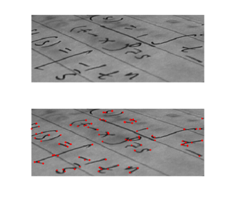
Corner detection is an approach used within computer vision systems to extract certain kinds of features and infer the contents of an image. Corner detection is frequently used in motion detection, image registration, video tracking, image mosaicing, panorama stitching, 3D reconstruction and object recognition. Corner detection overlaps with the topic of interest point detection.

In geometry, various formalisms exist to express a rotation in three dimensions as a mathematical transformation. In physics, this concept is applied to classical mechanics where rotational kinematics is the science of quantitative description of a purely rotational motion. The orientation of an object at a given instant is described with the same tools, as it is defined as an imaginary rotation from a reference placement in space, rather than an actually observed rotation from a previous placement in space.

In computer vision, the essential matrix is a matrix, that relates corresponding points in stereo images assuming that the cameras satisfy the pinhole camera model.

<span class="mw-page-title-main">Image rectification</span>

Image rectification is a transformation process used to project images onto a common image plane. This process has several degrees of freedom and there are many strategies for transforming images to the common plane. Image rectification is used in computer stereo vision to simplify the problem of finding matching points between images, and in geographic information systems to merge images taken from multiple perspectives into a common map coordinate system.

In computer vision a camera matrix or (camera) projection matrix is a matrix which describes the mapping of a pinhole camera from 3D points in the world to 2D points in an image.

<span class="mw-page-title-main">Pinhole camera model</span> Model of 3D points projected onto planar image via a lens-less aperture

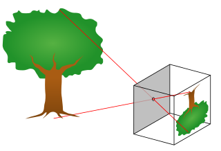
The pinhole camera model describes the mathematical relationship between the coordinates of a point in three-dimensional space and its projection onto the image plane of an ideal pinhole camera, where the camera aperture is described as a point and no lenses are used to focus light. The model does not include, for example, geometric distortions or blurring of unfocused objects caused by lenses and finite sized apertures. It also does not take into account that most practical cameras have only discrete image coordinates. This means that the pinhole camera model can only be used as a first order approximation of the mapping from a 3D scene to a 2D image. Its validity depends on the quality of the camera and, in general, decreases from the center of the image to the edges as lens distortion effects increase.

In computer vision, triangulation refers to the process of determining a point in 3D space given its projections onto two, or more, images. In order to solve this problem it is necessary to know the parameters of the camera projection function from 3D to 2D for the cameras involved, in the simplest case represented by the camera matrices. Triangulation is sometimes also referred to as reconstruction or intersection.

Camera auto-calibration is the process of determining internal camera parameters directly from multiple uncalibrated images of unstructured scenes. In contrast to classic camera calibration, auto-calibration does not require any special calibration objects in the scene. In the visual effects industry, camera auto-calibration is often part of the "Match Moving" process where a synthetic camera trajectory and intrinsic projection model are solved to reproject synthetic content into video.

<span class="mw-page-title-main">3D reconstruction from multiple images</span> Creation of a 3D model from a set of images

3D reconstruction from multiple images is the creation of three-dimensional models from a set of images. It is the reverse process of obtaining 2D images from 3D scenes.

In image processing, a kernel, convolution matrix, or mask is a small matrix used for blurring, sharpening, embossing, edge detection, and more. This is accomplished by doing a convolution between the kernel and an image. Or more simply, when each pixel in the output image is a function of the nearby pixels in the input image, the kernel is that function.

Chessboards arise frequently in computer vision theory and practice because their highly structured geometry is well-suited for algorithmic detection and processing. The appearance of chessboards in computer vision can be divided into two main areas: camera calibration and feature extraction. This article provides a unified discussion of the role that chessboards play in the canonical methods from these two areas, including references to the seminal literature, examples, and pointers to software implementations.

In computer vision, rigid motion segmentation is the process of separating regions, features, or trajectories from a video sequence into coherent subsets of space and time. These subsets correspond to independent rigidly moving objects in the scene. The goal of this segmentation is to differentiate and extract the meaningful rigid motion from the background and analyze it. Image segmentation techniques labels the pixels to be a part of pixels with certain characteristics at a particular time. Here, the pixels are segmented depending on its relative movement over a period of time i.e. the time of the video sequence.

Perspective-n-Point is the problem of estimating the pose of a calibrated camera given a set of n 3D points in the world and their corresponding 2D projections in the image. The camera pose consists of 6 degrees-of-freedom (DOF) which are made up of the rotation and 3D translation of the camera with respect to the world. This problem originates from camera calibration and has many applications in computer vision and other areas, including 3D pose estimation, robotics and augmented reality. A commonly used solution to the problem exists for n = 3 called P3P, and many solutions are available for the general case of n ≥ 3. A solution for n = 2 exists if feature orientations are available at the two points. Implementations of these solutions are also available in open source software.

References

  1. Richard Hartley and Andrew Zisserman (2003). Multiple View Geometry in Computer Vision. Cambridge University Press. pp. 155–157. ISBN   0-521-54051-8.
  2. Z. Zhang, "A flexible new technique for camera calibration'" Archived 2015-12-03 at the Wayback Machine , IEEE Transactions on Pattern Analysis and Machine Intelligence, Vol.22, No.11, pages 13301334, 2000
  3. P. Sturm and S. Maybank, "On plane-based camera calibration: a general algorithm, singularities, applications'" Archived 2016-03-04 at the Wayback Machine , In Proceedings of the IEEE Conference on Computer Vision and Pattern Recognition (CVPR), pages 432437, Fort Collins, CO, USA, June 1999
  4. Abdel-Aziz, Y.I., Karara, H.M. "Direct linear transformation from comparator coordinates into object space coordinates in close-range photogrammetry Archived 2019-08-02 at the Wayback Machine ", Proceedings of the Symposium on Close-Range Photogrammetry (pp. 1-18), Falls Church, VA: American Society of Photogrammetry, (1971)
  5. Roger Y. Tsai, "A Versatile Camera Calibration Technique for High-Accuracy 3D Machine Vision Metrology Using Off-the-Shelf TV Cameras and Lenses," IEEE Journal of Robotics and Automation, Vol. RA-3, No.4, August 1987
  6. Boris Peter Selby et al., "Patient positioning with X-ray detector self-calibration for image guided therapy" Archived 2023-11-10 at the Wayback Machine , Australasian Physical & Engineering Science in Medicine, Vol.34, No.3, pages 391400, 2011