In telecommunication and electrical engineering, a phantom circuit is an electrical circuit derived from suitably arranged wires with one or more conductive paths being a circuit in itself and at the same time acting as one conductor of another circuit.

A rectifier is an electrical device that converts alternating current (AC), which periodically reverses direction, to direct current (DC), which flows in only one direction. The reverse operation is performed by the inverter.
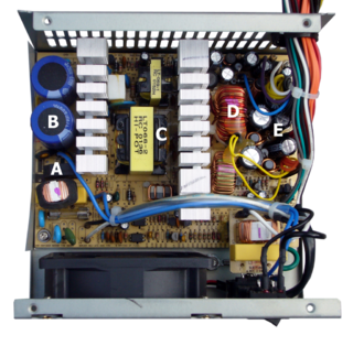
A switched-mode power supply is an electronic power supply that incorporates a switching regulator to convert electrical power efficiently.

A balun is an electrical device that allows balanced and unbalanced lines to be interfaced without disturbing the impedance arrangement of either line. A balun can take many forms and may include devices that also transform impedances but need not do so. Sometimes, in the case of transformer baluns, they use magnetic coupling but need not do so. Common-mode chokes are also used as baluns and work by eliminating, rather than rejecting, common mode signals.
The Hartley oscillator is an electronic oscillator circuit in which the oscillation frequency is determined by a tuned circuit consisting of capacitors and inductors, that is, an LC oscillator. The circuit was invented in 1915 by American engineer Ralph Hartley. The distinguishing feature of the Hartley oscillator is that the tuned circuit consists of a single capacitor in parallel with two inductors in series, and the feedback signal needed for oscillation is taken from the center connection of the two inductors.

A voltage regulator is a system designed to automatically maintain a constant voltage. A voltage regulator may use a simple feed-forward design or may include negative feedback. It may use an electromechanical mechanism, or electronic components. Depending on the design, it may be used to regulate one or more AC or DC voltages.

A push–pull amplifier is a type of electronic circuit that uses a pair of active devices that alternately supply current to, or absorb current from, a connected load. This kind of amplifier can enhance both the load capacity and switching speed.

An autotransformer is an electrical transformer with only one winding. The "auto" prefix refers to the single coil acting alone, not to any kind of automatic mechanism. In an autotransformer, portions of the same winding act as both the primary winding and secondary winding sides of the transformer. In contrast, an ordinary transformer has separate primary and secondary windings which have no metallic conducting path between them.

A flyback transformer (FBT), also called a line output transformer (LOPT), is a special type of electrical transformer. It was initially designed to generate high voltage sawtooth signals at a relatively high frequency. In modern applications, it is used extensively in switched-mode power supplies for both low (3 V) and high voltage supplies.
A welding power supply is a device that provides or modulates an electric current to perform arc welding. There are multiple arc welding processes in common use ranging from relatively simple Shielded Metal Arc Welding (SMAW) to more complicated welding processes using inert shielding gas like Gas metal arc welding (GMAW) or Gas tungsten arc welding (GTAW). Welding power supplies primarily serve as devices that allow a welder to exercise control over whether current is alternating current (AC) or direct current (DC), as well as the amount of current and voltage. Power supplies for welding processes that use shielding gas also offer connections for gas and methods to control gas flow. The operator can set these factors to within the parameters as needed by the metal type, thickness, and technique to be used. The majority of welding power supplies do not generate power, instead functioning as controllable transformers that allow the operator to adjust electrical properties as needed. However, in some welding applications, notably SMAW, used in areas isolated from power grids, welding power supplies are used that combine the functions of electrical generation and current modulation into a single mobile unit mounted on a vehicle or towed trailer.

An electronic component is any basic discrete device or physical entity in an electronic system used to affect electrons or their associated fields. Electronic components are mostly industrial products, available in a singular form and are not to be confused with electrical elements, which are conceptual abstractions representing idealized electronic components and elements.

A tap changer is a mechanism in transformers which allows for variable turn ratios to be selected in distinct steps. This is done by connecting to a number of access points known as taps along either the primary or secondary winding.

An electronic symbol is a pictogram used to represent various electrical and electronic devices or functions, such as wires, batteries, resistors, and transistors, in a schematic diagram of an electrical or electronic circuit. These symbols are largely standardized internationally today, but may vary from country to country, or engineering discipline, based on traditional conventions.

A push–pull converter is a type of DC-to-DC converter, a switching converter that uses a transformer to change the voltage of a DC power supply. The distinguishing feature of a push-pull converter is that the transformer primary is supplied with current from the input line by pairs of transistors in a symmetrical push-pull circuit. The transistors are alternately switched on and off, periodically reversing the current in the transformer. Therefore, current is drawn from the line during both halves of the switching cycle. This contrasts with buck-boost converters, in which the input current is supplied by a single transistor which is switched on and off, so current is only drawn from the line during half the switching cycle. During the other half the output power is supplied by energy stored in inductors or capacitors in the power supply. Push–pull converters have steadier input current, create less noise on the input line, and are more efficient in higher power applications.

In electronics, biasing is the setting of DC operating conditions of an active device in an amplifier. Many electronic devices, such as diodes, transistors and vacuum tubes, whose function is processing time-varying (AC) signals, also require a steady (DC) current or voltage at their terminals to operate correctly. This current or voltage is called bias. The AC signal applied to them is superposed on this DC bias current or voltage.

A variety of types of electrical transformer are made for different purposes. Despite their design differences, the various types employ the same basic principle as discovered in 1831 by Michael Faraday, and share several key functional parts.
The Ampeg SVT is a bass guitar amplifier designed by Bill Hughes and Roger Cox for Ampeg and introduced in 1969. The SVT is a stand-alone amplifier or "head" as opposed to a "combo" unit comprising amp and speaker(s) in one cabinet, and was capable of 300 watts output at a time when most amplifiers could not exceed 100 watts output, making the SVT an important amp for bands playing music festivals and other large venues. The SVT has been through many design changes over the years but is still in production today. While the SVT could be used with any 300 watt, 2- or 4-ohm cabinet combination, Ampeg recommended that it be used with a pair of sealed 8x10" speaker enclosures because one cabinet could not handle the power of the SVT. It wasn't until 1980 that the speakers in the enclosures were updated to a power handling rating of 350 watts, allowing a player to use an SVT head with only one cabinet!
A Royer oscillator is an electronic relaxation oscillator that employs a saturable-core transformer. It was invented and patented in 1954 by George H. Royer. It has the advantages of simplicity, low component count, rectangle waveforms, and easy transformer isolation. By making maximum use of the transformer core, it also minimises the size and weight of the transformer. The classic Royer circuit outputs square waves. There is another converter design often described as a "resonant Royer" which generates sinewaves. This was, apparently, first described in 1959 by Baxandall and therefore should be called the "Baxandall converter". Its differences are explained below. Both versions are widely used, mainly as power inverters.

Tube sound is the characteristic sound associated with a vacuum tube amplifier, a vacuum tube-based audio amplifier. At first, the concept of tube sound did not exist, because practically all electronic amplification of audio signals was done with vacuum tubes and other comparable methods were not known or used. After introduction of solid state amplifiers, tube sound appeared as the logical complement of transistor sound, which had some negative connotations due to crossover distortion in early transistor amplifiers. However, solid state amplifiers have been developed to be flawless and the sound is later regarded neutral compared to tube amplifiers. Thus the tube sound now means 'euphonic distortion.' The audible significance of tube amplification on audio signals is a subject of continuing debate among audio enthusiasts.

In electrical engineering, the Korndorfer starter is a technique used for reduced voltage soft starting of induction motors. The circuit uses a three-phase autotransformer and three three-phase switches. This motor starting method has been updated and improved by Hilton Raymond Bacon.

