
An electric motor is an electrical machine that converts electrical energy into mechanical energy. Most electric motors operate through the interaction between the motor's magnetic field and electric current in a wire winding to generate force in the form of torque applied on the motor's shaft. An electric generator is mechanically identical to an electric motor, but operates with a reversed flow of power, converting mechanical energy into electrical energy.
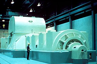
In electricity generation, a generator is a device that converts motive power or fuel-based power into electric power for use in an external circuit. Sources of mechanical energy include steam turbines, gas turbines, water turbines, internal combustion engines, wind turbines and even hand cranks. The first electromagnetic generator, the Faraday disk, was invented in 1831 by British scientist Michael Faraday. Generators provide nearly all of the power for electric power grids.

A stepper motor, also known as step motor or stepping motor, is a brushless DC electric motor that divides a full rotation into a number of equal steps. The motor's position can be commanded to move and hold at one of these steps without any position sensor for feedback, as long as the motor is correctly sized to the application in respect to torque and speed.

A commutator is a rotary electrical switch in certain types of electric motors and electrical generators that periodically reverses the current direction between the rotor and the external circuit. It consists of a cylinder composed of multiple metal contact segments on the rotating armature of the machine. Two or more electrical contacts called "brushes" made of a soft conductive material like carbon press against the commutator, making sliding contact with successive segments of the commutator as it rotates. The windings on the armature are connected to the commutator segments.

The stator is the stationary part of a rotary system, found in electric generators, electric motors, sirens, mud motors or biological rotors. Energy flows through a stator to or from the rotating component of the system. In an electric motor, the stator provides a magnetic field that drives the rotating armature; in a generator, the stator converts the rotating magnetic field to electric current. In fluid powered devices, the stator guides the flow of fluid to or from the rotating part of the system.

An induction motor or asynchronous motor is an AC electric motor in which the electric current in the rotor needed to produce torque is obtained by electromagnetic induction from the magnetic field of the stator winding. An induction motor can therefore be made without electrical connections to the rotor. An induction motor's rotor can be either wound type or squirrel-cage type.

A synchronous electric motor is an AC electric motor in which, at steady state, the rotation of the shaft is synchronized with the frequency of the supply current; the rotation period is exactly equal to an integral number of AC cycles. Synchronous motors use electromagnets as the stator of the motor which create a magnetic field that rotates in time with the oscillations of the current. The rotor with permanent magnets or electromagnets turns in step with the stator field at the same rate and as a result, provides the second synchronized rotating magnet field. A synchronous motor is termed doubly fed if it is supplied with independently excited multiphase AC electromagnets on both the rotor and stator.
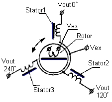
A synchro is, in effect, a transformer whose primary-to-secondary coupling may be varied by physically changing the relative orientation of the two windings. Synchros are often used for measuring the angle of a rotating machine such as an antenna platform or transmitting rotation. In its general physical construction, it is much like an electric motor. The primary winding of the transformer, fixed to the rotor, is excited by an alternating current, which by electromagnetic induction, causes voltages to appear between the Y-connected secondary windings fixed at 120 degrees to each other on the stator. The voltages are measured and used to determine the angle of the rotor relative to the stator.
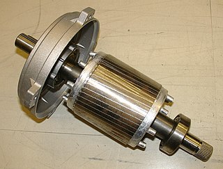
A squirrel-cage rotor is the rotating part of the common squirrel-cage induction motor. It consists of a cylinder of steel laminations, with aluminum or copper conductors embedded in its surface. In operation, the non-rotating stator winding is connected to an alternating current power source; the alternating current in the stator produces a rotating magnetic field. The rotor winding has current induced in it by the stator field, like a transformer except that the current in the rotor is varying at the stator field rotation rate minus the physical rotation rate. The interaction of the magnetic fields of currents in the stator and rotor produce a torque on the rotor.

A rotary converter is a type of electrical machine which acts as a mechanical rectifier, inverter or frequency converter.
Torsional vibration is angular vibration of an object—commonly a shaft along its axis of rotation. Torsional vibration is often a concern in power transmission systems using rotating shafts or couplings where it can cause failures if not controlled. A second effect of torsional vibrations applies to passenger cars. Torsional vibrations can lead to seat vibrations or noise at certain speeds. Both reduce the comfort.

In electrical engineering, the armature is the winding of an electric machine which carries alternating current. The armature windings conduct AC even on DC machines, due to the commutator action or due to electronic commutation, as in brushless DC motors. The armature can be on either the rotor or the stator, depending on the type of electric machine.

A reluctance motor is a type of electric motor that induces non-permanent magnetic poles on the ferromagnetic rotor. The rotor does not have any windings. It generates torque through magnetic reluctance.

An AC motor is an electric motor driven by an alternating current (AC). The AC motor commonly consists of two basic parts, an outside stator having coils supplied with alternating current to produce a rotating magnetic field, and an inside rotor attached to the output shaft producing a second rotating magnetic field. The rotor magnetic field may be produced by permanent magnets, reluctance saliency, or DC or AC electrical windings.
An induction generator or asynchronous generator is a type of alternating current (AC) electrical generator that uses the principles of induction motors to produce electric power. Induction generators operate by mechanically turning their rotors faster than synchronous speed. A regular AC induction motor usually can be used as a generator, without any internal modifications. Because they can recover energy with relatively simple controls, induction generators are useful in applications such as mini hydro power plants, wind turbines, or in reducing high-pressure gas streams to lower pressure.

The rotor is a moving component of an electromagnetic system in the electric motor, electric generator, or alternator. Its rotation is due to the interaction between the windings and magnetic fields which produces a torque around the rotor's axis.
In electrical engineering, electric machine is a general term for machines using electromagnetic forces, such as electric motors, electric generators, and others. They are electromechanical energy converters: an electric motor converts electricity to mechanical power while an electric generator converts mechanical power to electricity. The moving parts in a machine can be rotating or linear. Besides motors and generators, a third category often included is transformers, which although they do not have any moving parts are also energy converters, changing the voltage level of an alternating current.

The switched reluctance motor (SRM) is an electric motor that runs by reluctance torque. Unlike common brushed DC motor types, power is delivered to windings in the stator (case) rather than the rotor. This greatly simplifies mechanical design as power does not have to be delivered to a moving part which eliminates the need for a commutator, but it complicates the electrical design as some sort of switching system needs to be used to deliver power to the different windings. Electronic devices can precisely time the switching of currents, facilitating SRM configurations. Its main drawback is torque ripple. Controller technology that limits torque ripple at low speeds has been demonstrated. Sources disagree on whether it is a type of stepper motor.
A permanent magnet synchronous generator is a generator where the excitation field is provided by a permanent magnet instead of a coil. The term synchronous refers here to the fact that the rotor and magnetic field rotate with the same speed, because the magnetic field is generated through a shaft mounted permanent magnet mechanism and current is induced into the stationary armature.
The reactances of synchronous machines comprise a set of characteristic constants used in the theory of synchronous machines. Technically, these constants are specified in units of the electrical reactance (ohms), although they are typically expressed in the per-unit system and thus dimensionless. Since for practically all machines the resistance of the coils is negligibly small in comparison to the reactance, the latter can be used instead of (complex) electrical impedance, simplifying the calculations.
