In electronics, an analog-to-digital converter is a system that converts an analog signal, such as a sound picked up by a microphone or light entering a digital camera, into a digital signal. An ADC may also provide an isolated measurement such as an electronic device that converts an analog input voltage or current to a digital number representing the magnitude of the voltage or current. Typically the digital output is a two's complement binary number that is proportional to the input, but there are other possibilities.
Dynamic range is the ratio between the largest and smallest values that a certain quantity can assume. It is often used in the context of signals, like sound and light. It is measured either as a ratio or as a base-10 (decibel) or base-2 logarithmic value of the ratio between the largest and smallest signal values.
Signal-to-noise ratio is a measure used in science and engineering that compares the level of a desired signal to the level of background noise. SNR is defined as the ratio of signal power to noise power, often expressed in decibels. A ratio higher than 1:1 indicates more signal than noise.

Image compression is a type of data compression applied to digital images, to reduce their cost for storage or transmission. Algorithms may take advantage of visual perception and the statistical properties of image data to provide superior results compared with generic data compression methods which are used for other digital data.

Halftone is the reprographic technique that simulates continuous-tone imagery through the use of dots, varying either in size or in spacing, thus generating a gradient-like effect. "Halftone" can also be used to refer specifically to the image that is produced by this process.
Sound can be recorded and stored and played using either digital or analog techniques. Both techniques introduce errors and distortions in the sound, and these methods can be systematically compared. Musicians and listeners have argued over the superiority of digital versus analog sound recordings. Arguments for analog systems include the absence of fundamental error mechanisms which are present in digital audio systems, including aliasing and associated anti-aliasing filter implementation, jitter and quantization noise. Advocates of digital point to the high levels of performance possible with digital audio, including excellent linearity in the audible band and low levels of noise and distortion.
A compression artifact is a noticeable distortion of media caused by the application of lossy compression. Lossy data compression involves discarding some of the media's data so that it becomes small enough to be stored within the desired disk space or transmitted (streamed) within the available bandwidth. If the compressor cannot store enough data in the compressed version, the result is a loss of quality, or introduction of artifacts. The compression algorithm may not be intelligent enough to discriminate between distortions of little subjective importance and those objectionable to the user.

In signal processing, sampling is the reduction of a continuous-time signal to a discrete-time signal. A common example is the conversion of a sound wave to a sequence of "samples". A sample is a value of the signal at a point in time and/or space; this definition differs from the term's usage in statistics, which refers to a set of such values.

Audio system measurements are a means of quantifying system performance. These measurements are made for several purposes. Designers take measurements so that they can specify the performance of a piece of equipment. Maintenance engineers make them to ensure equipment is still working to specification, or to ensure that the cumulative defects of an audio path are within limits considered acceptable. Audio system measurements often accommodate psychoacoustic principles to measure the system in a way that relates to human hearing.
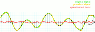
Quantization, in mathematics and digital signal processing, is the process of mapping input values from a large set to output values in a (countable) smaller set, often with a finite number of elements. Rounding and truncation are typical examples of quantization processes. Quantization is involved to some degree in nearly all digital signal processing, as the process of representing a signal in digital form ordinarily involves rounding. Quantization also forms the core of essentially all lossy compression algorithms.
Quantization, involved in image processing, is a lossy compression technique achieved by compressing a range of values to a single quantum (discrete) value. When the number of discrete symbols in a given stream is reduced, the stream becomes more compressible. For example, reducing the number of colors required to represent a digital image makes it possible to reduce its file size. Specific applications include DCT data quantization in JPEG and DWT data quantization in JPEG 2000.
Noise shaping is a technique typically used in digital audio, image, and video processing, usually in combination with dithering, as part of the process of quantization or bit-depth reduction of a signal. Its purpose is to increase the apparent signal-to-noise ratio of the resultant signal. It does this by altering the spectral shape of the error that is introduced by dithering and quantization; such that the noise power is at a lower level in frequency bands at which noise is considered to be less desirable and at a correspondingly higher level in bands where it is considered to be more desirable. A popular noise shaping algorithm used in image processing is known as ‘Floyd Steinberg dithering’; and many noise shaping algorithms used in audio processing are based on an ‘Absolute threshold of hearing’ model.
In signal processing, oversampling is the process of sampling a signal at a sampling frequency significantly higher than the Nyquist rate. Theoretically, a bandwidth-limited signal can be perfectly reconstructed if sampled at the Nyquist rate or above it. The Nyquist rate is defined as twice the bandwidth of the signal. Oversampling is capable of improving resolution and signal-to-noise ratio, and can be helpful in avoiding aliasing and phase distortion by relaxing anti-aliasing filter performance requirements.

Floyd–Steinberg dithering is an image dithering algorithm first published in 1976 by Robert W. Floyd and Louis Steinberg. It is commonly used by image manipulation software, for example when an image is converted into GIF format that is restricted to a maximum of 256 colors.

Image noise is random variation of brightness or color information in images, and is usually an aspect of electronic noise. It can be produced by the image sensor and circuitry of a scanner or digital camera. Image noise can also originate in film grain and in the unavoidable shot noise of an ideal photon detector. Image noise is an undesirable by-product of image capture that obscures the desired information. Typically the term “image noise” is used to refer to noise in 2D images, not 3D images.
In computer graphics, color quantization or color image quantization is quantization applied to color spaces; it is a process that reduces the number of distinct colors used in an image, usually with the intention that the new image should be as visually similar as possible to the original image. Computer algorithms to perform color quantization on bitmaps have been studied since the 1970s. Color quantization is critical for displaying images with many colors on devices that can only display a limited number of colors, usually due to memory limitations, and enables efficient compression of certain types of images.

In digital audio using pulse-code modulation (PCM), bit depth is the number of bits of information in each sample, and it directly corresponds to the resolution of each sample. Examples of bit depth include Compact Disc Digital Audio, which uses 16 bits per sample, and DVD-Audio and Blu-ray Disc, which can support up to 24 bits per sample.

ImageMagick, invoked from the command line as magick, is a free and open-source cross-platform software suite for displaying, creating, converting, modifying, and editing raster images. ImageMagick was created by John Cristy in 1987, it can read and write over 200 image file formats. It is widely used in open-source applications.

Error diffusion is a type of halftoning in which the quantization residual is distributed to neighboring pixels that have not yet been processed. Its main use is to convert a multi-level image into a binary image, though it has other applications.

Ordered dithering is an image dithering algorithm. It is commonly used to display a continuous image on a display of smaller color depth. For example, Microsoft Windows uses it in 16-color graphics modes. The algorithm is characterized by noticeable crosshatch patterns in the result.


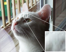 Figure 1. Original photo; note the smoothness in the detail.
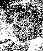
 Figure 2. Original image using the web-safe color palette with no dithering applied. Note the large flat areas and loss of detail.
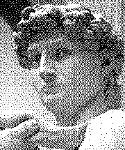
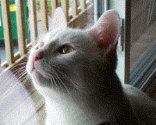 Figure 3. Original image using the web-safe color palette with Floyd–Steinberg dithering. Note that even though the same palette is used, the application of dithering gives a better representation of the original.
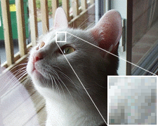 Figure 4. Here, the original has been reduced to a 256-color optimized palette with Floyd–Steinberg dithering applied. The use of an optimized palette, rather than a fixed palette, allows the result to better represent the colors in the original image.
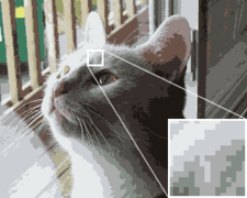 Figure 5. Depth is reduced to a 16-color optimized palette in this image, with no dithering. Colors appear muted, and color banding is pronounced.
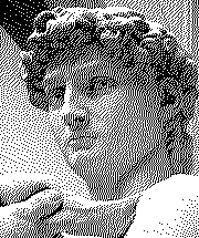
 Figure 6. This image also uses the 16-color optimized palette, but the use of dithering helps to reduce banding.